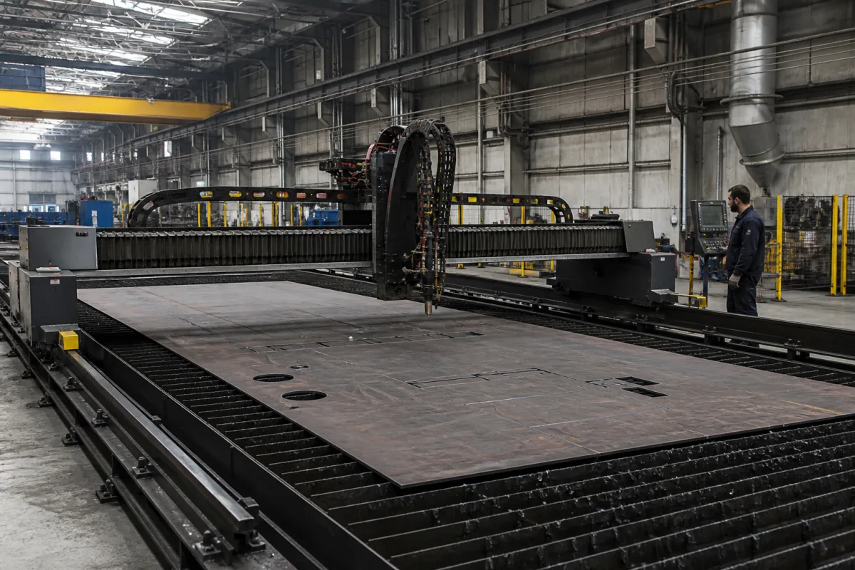
Cutting gantry: the beam, end carriages and rail track that carry the torches, specified apart from the cutting process
The moving portal of a shape-cutting machine · cross beam, end carriages, floor rail track and the two longitudinal drives that must stay in step
Strip the torch, power source, height control and table off a shape-cutting machine and what remains is the gantry: a stiff cross beam, two end carriages, the rail track they run on and the motors that push them. It decides how wide a plate the torches can reach, how far the machine has to travel past the plate, and whether both ends of the beam arrive together. Those properties belong in the order whatever cutting process is fitted later.
The portal (bridge) structure of CNC thermal shape-cutting machines: cross beam, end carriages, longitudinal rail track with its rack, the bilateral longitudinal drives, the transverse carriage guidance and cable chains, sized by rail span, travel length and the number of tool stations. Complete plasma cutting machines with their source, torch package, height control and cut-quality acceptance are covered on the CNC gantry plasma cutting machine page; the power source on the Plasma power supply page; machine torches and their consumable wear on the Cutting torch for CNC plasma machines page; slat beds, water and downdraft tables on the Plasma cutting table page; arc-voltage height control and Z lifters on the Plasma torch height controller page.
CNFX editorial research · Sources checked October 12, 2026 · 4 sources
Nominal size, overall width and torch reach: where the 800 mm goes in one portal range
ESAB's SUPRAREX SXE-P brochure gives a size table that shows how a gantry's footprint relates to the plate it can cut. Nominal machine sizes of 3,000, 4,500, 4,000, 5,500, 5,000 and 7,000 mm (8,000 mm on request) come with overall machine widths of 3,650 to 7,650 mm, a machine height of 2,000 mm, a machine dead length of 2,000 mm and a work support height of 700 mm. With one single torch, cutting width runs from 2,200 mm on the 3,000 size to 6,200 mm on the 7,000 size. [1]
Editorial calculation from that table: in every listed size the single-torch cutting width is 800 mm less than the nominal size (3,000 − 2,200; 7,000 − 6,200), and the overall machine width is 650 mm more than it (3,650 − 3,000; 7,650 − 7,000). On the smallest size, one torch therefore reaches about 60% of the overall machine width (2,200 / 3,650). [1]
The same table shows the beam being shared out between carriages: two torches cutting identical parts cover 2 × 1,100 mm on the 3,000 size, six cover 6 × 365 mm, eight single-torch carriages need an SXE-P 2 or 3 frame and twelve an SXE-P 3. Single-torch oxy-fuel cutting thickness is listed as 3 to 200 mm, falling to 3 to 50 mm with six torches and 3 to 40 mm with eight. [1]
ESAB describes the three SUPRAREX types as differing in the dimensions of the portal beam, the size of the working area and the type and complexity of the cutting tools, and says the beam and cutting carriage are laid out so the carriage can park outside the working area, with drives and side carriages placed centrally to cut the machine's dead length. [1]
State the largest plate width and the number of torches that must cut it at once; ask the builder for the resulting rail span, overall width and the length of rail needed beyond the plate at each end.
02
Two longitudinal drives on one beam: how a carriage moving along the beam pulls them out of step
A gantry beam is pushed by a motor at each end. Xie and Wang, modelling a dual-drive gantry with linear motors on two parallel rails, explain that when a heavy load such as a cutting head moves along the cross beam, the share of load carried by each motor changes, which produces synchronization error between the two ends and affects machining accuracy. [3]
Their simulation model is small: a 0.8 m cross beam of 25 kg including a 10 kg load, motors with a thrust constant of 61.0 N/A, and a beam-to-rail joint stiffness of 52,520 N/m. With the load near one motor, the maximum difference between the two axis positions after a position step command was 0.76 mm with a GSLQR optimal controller, 0.54 mm with a thrust-allocation method and 0.22 mm with the authors' force-feed-forward decoupling method; with the load near the other motor the figures were 0.39, 0.26 and 0.11 mm. The authors report these as simulation results and state that experimental verification would need the real system's parameters identified first. [3]
Editorial note: the figures come from a laboratory-scale model, not a production cutting gantry, so they illustrate the mechanism rather than an expected value. What a buyer can take from them is that the controller's handling of an off-centre carriage matters, and that the test of a two-sided drive should be run with the heaviest tool carriage parked at each end of the beam in turn.
Buyers already write the two-sided drive into their tenders. CSIR-National Metallurgical Laboratory's specification for a gantry plasma cutting machine asks for high-speed positive bilateral longitudinal drives, servo motors and double-side rack and pinion transmission for the gantry, and ESAB states that double drive systems are standard across the SUPRAREX range. [2][1]
Ask how the two longitudinal axes are coupled in the control (master-slave, cross-coupled or another scheme), how the beam is squared after power-up, and what difference between the two ends the builder guarantees with the heaviest carriage at either end.
03
Rail track and rack: hardened rails, rail height above the floor, and rack pitch error per metre of travel
The rail track sets the straightness the whole gantry runs on. CSIR-NML's specification calls for gantries fitted with hardened and ground rails on rigid H beams with fixing and levelling components, a top-of-rail height of at least 500 mm, longitudinal and transverse drive speeds of at least 15 m/min, a torch lifting height of at least 150 mm, and cable track chains on the X and Y axes, with a total width under 3,600 mm and a total length of up to 5,000 mm in its work-area lines. [2]
ESAB describes its track as heavy-duty railway rail accurately machined for the purpose, with all power and supply cables and hoses carried through cable chains, and quotes positioning speed of up to 20,000 mm/min for the range. [1]
The rack bolted beside the rail turns motor rotation into travel. ATLANTA's Q6 high-precision rack, as listed by its distributor Bibus, has a total pitch error of at most 0.034 mm per 1,000 mm, a tooth thickness tolerance of −20 µm and comes in lengths up to 2,000 mm, modules 1.5 to 12, with teeth hardened and ground on all sides. [4]
Editorial calculation: a 10 m longitudinal run built from 2,000 mm Q6 racks needs five pieces and four butt joints. If the per-metre pitch error added up in one direction with no correction at the joints, it would reach about 0.34 mm over 10 m (10 × 0.034). That is an upper bound under a stated assumption; ask how the joints are set and whether the controller compensates pitch error along the track. [4]
Cut quality on finished parts is specified separately: the NML tender refers vendors to DIN EN ISO 9013 for cutting accuracy, a standard for thermal cuts rather than for the gantry's own motion. [2]
Fix in the order: rail length and gauge, rail section and how it is machined, rail height above the floor, foundation and levelling method, rack quality class and piece length, how rack joints are aligned, and the drive speeds on both axes.
04
Plate size, torch count and track data for a cutting gantry
Paste it into your enquiry below or into an email to a maker, then replace every bracket.
Plate: [largest width and length to be cut]
Torches: [number and type of carriages; how many cut at once]
Rail span and travel: [gauge; total rail length; parking zone]
Track: [rail section; machined or ground; height above floor; foundation]
Rack: [quality class; module; piece length; joint alignment]
Drives: [bilateral longitudinal; servo type; speeds X and Y]
Synchronization: [coupling scheme; guaranteed end-to-end difference]
Cabling: [cable chains on X and Y; hoses carried]
Acceptance: [motion tests with heaviest carriage at each beam end]
Explore company information and manufacturing capabilities, then discuss the scope of your project with a relevant supplier.
Share this page
Compiled and source-reviewed by the CNFX editorial team.
Each manufacturer above links to the page on that company's own website where the product is listed, with the date we checked it. How we source and review
· Page last updated 13 October 2026
Buyer questions
How much narrower is the cutting width than the gantry size?
In ESAB's SUPRAREX SXE-P table, single-torch cutting width is 800 mm less than the nominal machine size in every listed size, for example 2,200 mm on the 3,000 size (editorial calculation from the table). [1]
Why do two-sided gantry drives fall out of step?
Xie and Wang show that as a heavy load moves along the cross beam the load shared by each motor changes, which produces synchronization error between the two ends. [3]
What does a buyer specify for the rail track?
One CSIR-NML tender asks for hardened and ground rails on rigid H beams with levelling components, top-of-rail height of at least 500 mm and double-side rack and pinion drive. [2]
How accurate is a precision gantry rack?
ATLANTA's Q6 rack is listed with a total pitch error of at most 0.034 mm per 1,000 mm and lengths up to 2,000 mm. [4]
Sources and what still needs a direct check
Sources checked 2026-10-12. Gantry sizes and drive layout come from an ESAB SUPRAREX SXE-P brochure; buyer requirements from a CSIR-National Metallurgical Laboratory tender specification; the synchronization mechanism from a 2022 paper in Entropy; rack accuracy from ATLANTA's Q6 rack listing at Bibus.