Editorial Technical Reference

Dampers/Valves

This page explains how Dampers/Valves is classified within Machinery and Equipment Manufacturing. Technical values and manufacturer relationships are research references; confirm the current specification and supplier evidence for each order.

Technical Definition & Core Assembly

Flow control devices in exhaust systems that regulate, redirect, or isolate gas streams.
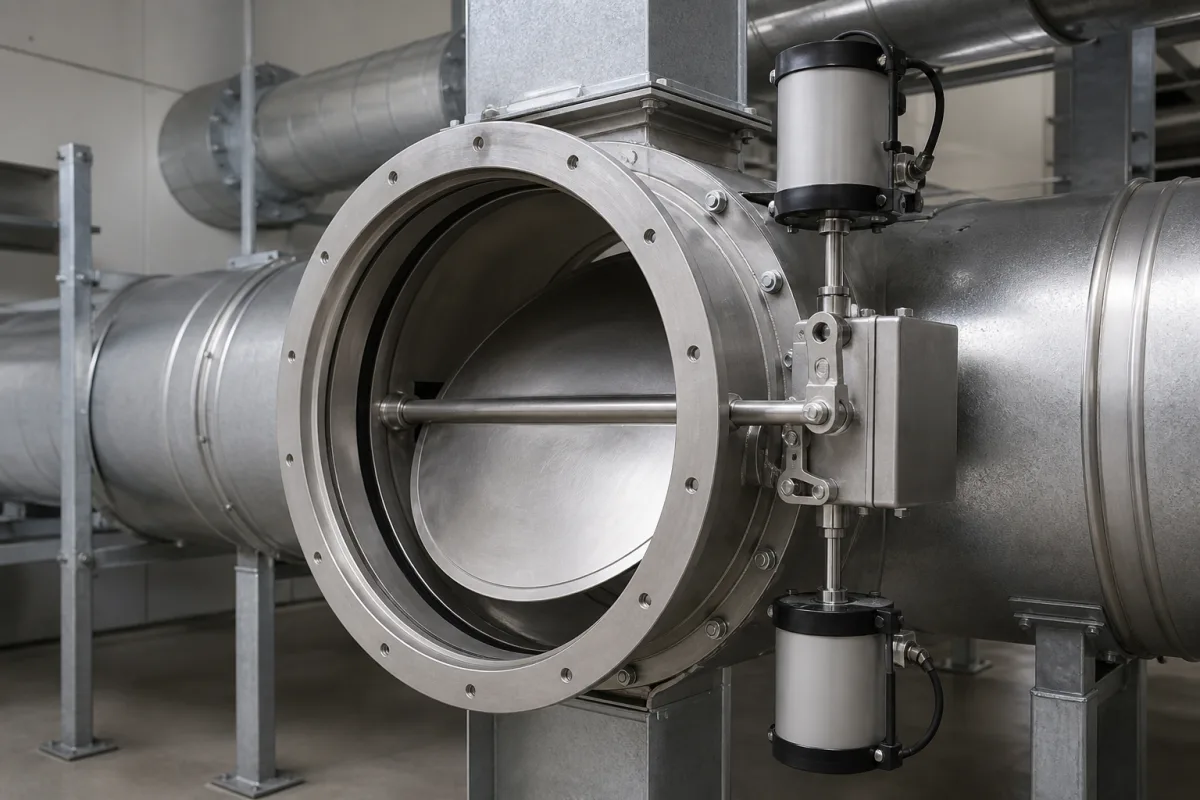
Dampers/Valves in a manufacturing environment
Representative product image. Confirm appearance and specifications with the manufacturer.

Product Specifications

Technical details and manufacturing context for Dampers/Valves

Definition
Dampers and valves are critical components within exhaust systems that control the flow, pressure, and direction of exhaust gases. Dampers typically function as adjustable louvers or blades to modulate airflow, while valves provide on/off isolation or directional control. They work together to manage system performance, energy efficiency, and safety by preventing backflow, balancing pressure, and directing emissions to appropriate treatment or discharge points. These components are available in various configurations and materials, including stainless steel, carbon steel, and aluminum alloys, to suit different operating environments. Key parameters for selection include nominal diameter (DN50–DN600 per ISO 6708), operating pressure (1.0–1.6 MPa), operating temperature (-40 to 85°C), leakage rate (0.01–0.1% per ISO 5208), actuation torque (50–500 N·m), response time (2–10 s), control signal (4–20 mA per IEC 60381), supply voltage (24 V DC ±10%), IP rating (IP54–IP65 per IEC 60529), body material (WCB or CF8M per ASTM A216/A351), seat material (PTFE or RPTFE per ASTM D3294), and weight (15–60 kg). These values are reference ranges and must be verified for the specific model and application. Dampers and valves are actuated manually, electrically, or pneumatically, depending on system requirements. Proper selection and maintenance are essential to ensure reliable operation, prevent leakage, and maintain system efficiency. Always consult the legal manufacturer or supplier to confirm model-specific values and compliance with applicable standards.
Working Principle
Dampers operate by rotating blades or louvers to increase or decrease the open cross-sectional area, thereby controlling airflow resistance. Valves use various mechanisms (butterfly, gate, ball) to completely open, close, or partially obstruct the flow path. Both are typically actuated manually, electrically, or pneumatically based on system requirements. The actuation torque and response time are critical for proper operation, and the control signal (4–20 mA) is used for analog control. The leakage rate indicates the sealing performance, and the IP rating defines protection against dust and water. The body and seat materials determine chemical resistance and friction characteristics. These components must be selected based on the specific process conditions, including pressure, temperature, and media compatibility.
Common Materials
Stainless steel, Carbon steel, Aluminum alloys
Technical Parameters
ParameterTypical rangeNotes & selection driver
Nominal DiameterDN50–DN600 mmStandard sizes for pipe connectionsISO 6708
Operating Temperature-40–85 °CSeal material limits range
Leakage Rate0.01–0.1 %Class IV or better
Actuation Torque50–500 N·mRequired for manual or motorized operation
Response Time2–10 sFull stroke time for actuators
Control Signal4–20 mAAnalog control standardIEC 60381
Supply Voltage24 ±10% V DCFor electric actuators
IP RatingIP54–IP65Dust and water protectionIEC 60529
Body MaterialWCB/CF8MCarbon steel or stainless steelASTM A216/A351
Seat MaterialPTFE/RPTFEChemical resistance and low frictionASTM D3294
Weight15–60 kgDepends on size and pressure class

Ranges are indicative industry figures for RFQ preparation, not a supplier commitment. Confirm every value and standard with the legal manufacturer before ordering.

Components / BOM
  • Blade/Louver Assembly
    Primary flow control element that rotates to modulate airflow
    Material: Stainless steel
  • Seal/Gasket Part
    Provides airtight closure when damper/valve is in closed position
    Material: Silicone rubber or high-temperature elastomer
  • Shaft Part
    Connects actuation mechanism to blades/louvers for rotational control
    Material: Carbon steel or stainless steel
  • Actuator
    Provides mechanical force to open, close, or modulate the damper/valve position
    Material: Aluminum housing with steel/internal components

Applied To / Applications

This component is essential for the following industrial systems and equipment:

Industrial Ecosystem & Supply Chain Structure

Complementary Systems
Downstream Applications
Specialized Tooling

Application Fit & Sizing Matrix

Operational Limits
pressure: Up to 10 bar (standard), up to 25 bar with reinforced designs
flow rate: 0.1 to 50 m³/s depending on valve size and type
temperature: -40°C to +85°C
slurry concentration: Up to 30% solids by weight (with abrasion-resistant linings)
Media Compatibility
✓ Industrial exhaust gases (combustion products) ✓ Process air streams ✓ Dry particulate-laden flows
Unsuitable: Highly corrosive chemical streams (e.g., concentrated acids, chlorine gas) without specialized corrosion-resistant materials
Sizing Data Required
  • Required flow rate (m³/s or CFM)
  • System pressure drop allowance (Pa or inches H₂O)
  • Gas temperature and composition (including particulate loading)

Reliability & Engineering Risk Analysis

Failure Mode & Root Cause
Sticking/Binding
Cause: Accumulation of particulate matter, corrosion products, or thermal expansion mismatches in valve stems, damper blades, or sealing surfaces, often exacerbated by inadequate lubrication or environmental contaminants.
Internal Leakage/Seat Erosion
Cause: Wear from abrasive media, cavitation in high-pressure drop applications, or chemical attack degrading valve seats, damper seals, or blade edges, leading to loss of shutoff capability.
Maintenance Indicators
  • Audible: Hissing or whistling sounds indicating gas or steam leakage past seals or seats.
  • Visual: External leakage of process fluid, or visible corrosion/cracking on valve bodies, damper housings, or actuator linkages.
Engineering Tips
  • Implement routine lubrication and cleaning schedules for moving parts, using compatible lubricants and ensuring seals are intact to prevent contaminant ingress.
  • Install strainers upstream to catch particulates, and consider upgrading to erosion/corrosion-resistant materials (e.g., hardened seats, stainless steel) for high-wear applications.

Indicative industry ranges for design and RFQ preparation. Confirm the exact figures and applicable standard with the manufacturer before specifying.

Compliance & Manufacturing Standards

Applicable Standards
ISO 5211:2017 - Industrial valves - Part-turn actuator attachments ANSI/FCI 70-2-2013 - Control Valve Seat Leakage DIN EN 593:2017 - Industrial valves - Metallic butterfly valves for general purposes

Quoted from the published standard.

Manufacturing Precision
  • Bore diameter: +/-0.05mm
  • Surface flatness: 0.08mm per 100mm
Quality Inspection
  • Hydrostatic pressure test (seat and shell)
  • Dye penetrant inspection for surface defects

Manufacturers of Dampers/Valves

1 company lists this product among what they make. Company figures are quoted from each company's own website; every card states where the relationship came from.

XICHENG EP LTD
Guangdong, CN
Also makes: Ventilation System, Water Pump, Water Tank and 1 more
Listed on the company's own website · profile compiled by CNFX from public sources
Listed there as: “Electric Motorized Dampers & Valves”
View source page ↗ plastic-xc.com · checked 2026-08-26

Manufacturer listings support early research and capability understanding. They are not certification, ranking, or transaction guarantees.

Share this page
Technical documentation
Request current drawings, revision history, and a signed specification sheet.
Manufacturing capability
Verify equipment lists, process limits, capacity, and representative production evidence.
Inspection readiness
Confirm test methods, calibrated equipment, sampling plans, and traceable reports.
Supplier transparency
Check the legal entity, factory address, ownership, certifications, and direct contacts.

CNFX does not score or rank suppliers. Buyers must verify all claims and documents with the legal manufacturer before ordering.

Supply Chain Compatible Machinery & Devices

Hydraulic Press

Industrial machine using hydraulic pressure to compress, form, or assemble materials

Explore Specs →
Heavy-Duty CNC Plasma Cutting Machine

The Heavy-Duty CNC Plasma Cutting Machine is a standalone industrial device designed for cutting conductive metals such as steel, stainless steel, aluminum, and copper alloys.

Explore Specs →
Automated Powder Coating System

Integrated industrial system for applying dry powder coatings to metal substrates.

Explore Specs →
Centrifugal Pump Impeller

The centrifugal pump impeller is a critical rotating component that converts mechanical energy from the motor into kinetic energy in fluid systems.

Explore Specs →

Frequently Asked Questions

What are the typical materials used for dampers and valves?

Common materials include stainless steel, carbon steel, and aluminum alloys. The body material may be WCB or CF8M, and seat material may be PTFE or RPTFE, as listed in the reference data.

What is the operating pressure range for these components?

The reference operating pressure range is 1.0 to 1.6 MPa. However, the actual range depends on the specific model and application, so always verify with the manufacturer.

How are dampers and valves actuated?

They can be actuated manually, electrically, or pneumatically. The actuation torque and response time are important parameters, with typical torque of 50–500 N·m and response time of 2–10 seconds.

What standards apply to these products?

Relevant standards include ISO 6708 for nominal diameter, ISO 5208 for leakage testing, IEC 60381 for control signal, IEC 60529 for IP rating, and ASTM A216/A351 for body material. These are reference standards; compliance must be confirmed with the supplier.

Data Basis

Editorial classification, named public sources where available, and source-reviewed manufacturer records.

Preliminary Technical Classification
This page supports structured research, RFQ preparation, and supplier evaluation. It does not replace buyer-led supplier qualification, standards review, or technical approval.
Buyer enquiry

Request manufacturing insight for Dampers/Valves

Ask for use case, specification boundaries, supplier type, and RFQ preparation information for this product.

Where it goes
Straight to the CNFX editorial desk, and to the manufacturer if this product is linked to a claimed profile. Nothing is broadcast to a supplier list.
Your details stay here
We do not sell or rent enquiry data, and we do not add you to a mailing list. Used only to answer this request.
No commission, no middleman
CNFX is a directory. We take no cut of any order and never negotiate on a supplier's behalf.
What we don't claim
A listing is not an endorsement. Qualify every supplier and verify every figure yourself before ordering.

Your business information is used only to process this request.

Thank you! Your message has been sent. We'll respond within 1–3 business days.
Sorry, we couldn't send your message. Please try again, or email us at [email protected].

Need to Manufacture Dampers/Valves?

Compare manufacturer profiles with relevant product and process capability.

Previous Product
Cylinder Body (Pneumatic)
Next Product
Data Preprocessor
Get QuotesChat