Motor-and-gearbox drive of a reciprocating metering pump: reduction ratio and stroke rate, stroke-length adjustment, and the rod force the drive must deliver
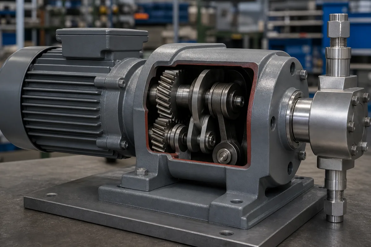
The power end of a motor-driven reciprocating metering pump · worm or spur reduction, crank or eccentric, return spring and stroke-length adjuster between the motor and the plunger
In a motor-driven metering pump the liquid end only displaces what the drive gives it. The motor's speed is cut down by a worm, spur or belt reduction, a crank, eccentric or cam turns rotation into a push on the plunger or diaphragm rod, and a stroke-length adjuster sets how much of that push reaches the liquid. The ratio fixes the stroke rate, the adjuster fixes the volume per stroke, and the motor and gearing have to carry the rod force at the highest discharge pressure. The figures below come from two maker data sheets and one maker patent.
Drive ends (power ends) of motor-driven reciprocating metering and dosing pumps: the motor, reduction gearing, crank, polar crank, eccentric or cam with return spring, crosshead or push rod, stroke-length adjuster and its manual, electric or pneumatic actuator, and stroke counting. General-purpose gear motors and motor–coupling–reducer drive assemblies for conveyors, mixers and drums are covered on the Gear motor drive assembly page; ATEX and Ex-marked motor-and-gearbox drives on the Explosion-protected motor and gearbox drive page; roller chain power transmission on its own page. The wetted pump head, valves and diaphragm are covered on the Dosing pump head (liquid end) page, and complete metering pumps with their accuracy, turndown and installation on the Metering pump page.
CNFX editorial research · Sources checked October 13, 2026 · 3 sources
Reduction ratio decides the stroke rate: 12.3:1 to 36:1 on a four-pole motor gives 142 down to 49 strokes per minute
Milton Roy builds its Milroyal B on one oil-bathed polar crank drive and lets the buyer pick the reduction ratio as a model-code option. The data sheet bases its performance tables on a 1725 rpm, three-phase, 60 Hz motor, marks the capacities as typ., and says to derate flow for other motor speeds. [1]
Editorial calculation: dividing 1725 rpm by each ratio gives 140, 111, 93, 69 and 48 strokes/min, one to two below the printed figures; dividing 1750 rpm (an example value, not stated in the sheet) by the same ratios gives 142, 113, 95, 70 and 49, matching the printed column. The sheet states 1725 rpm and prints strokes/min that fit 1750 rpm, so ask the supplier which motor speed the capacities assume. [1]
Editorial calculation: at gear code 8F the 1 in plunger's 148 l/h spread over 142 strokes × 60 min = 8,520 strokes per hour is 17.4 ml per stroke. Changing the ratio changes strokes per minute; the volume per stroke stays with the plunger and stroke setting. [1]
The same table shows the motor size climbing with discharge pressure at a fixed ratio: with the 1 in plunger at 8F, Milton Roy lists 285 psig (20 bar) on a 1/2 HP (0.37 kW) motor and 1,130 psig (78 bar) on 1 1/2 HP (1.1 kW). For single-phase motors it says to go up one horsepower size. [1]
Give the supplier the motor supply (voltage, phase, 50 or 60 Hz), the stroke rate you want at full output, and whether the ratio is to be chosen for slow strokes on viscous or gassing liquids or for fewer, larger strokes.
02
Stroke-length adjustment: a variable eccentric shortens a full sine stroke, a return stop or hydraulic bypass cuts part of it off
ProMinent's patent EP 1 754 891 B1 sets out the drive arrangements in use before its invention: asynchronous, synchronous or stepper motors; worm, spur-gear or belt reduction; and a spring/cam or eccentric that pushes a guided push rod, either positively driven both ways or driven forward only and pulled back by a return spring sized for the suction stroke. [3]
The patent describes two ways of setting stroke length. Changing the eccentricity, for example with a 'Taumelzylinder' of two inclined planes turned against each other, keeps the rod motion a pure sinusoid of smaller amplitude. An adjustable stop, a threaded stroke-setting pin with a knob and scale that halts the rod on its return before the eccentric's rear dead centre, keeps the full eccentric motion but cuts off its start; on hydraulically coupled heads a sliding sleeve uncovers a bypass bore in the rod after a set travel, so the end of the stroke is lost instead. It gives the forward (discharge) stroke as well under a second, around 200 ms as its example, with the peak liquid velocity near mid-stroke on an eccentric drive. [3]
The REKOS KR piston pump data sheet describes the stop type in hardware: an oil-filled worm gear drives a cam that pushes a spring-loaded plunger carrying the piston; the cam makes the metering stroke, the return spring the suction stroke, and a manually adjustable eccentric acts as the plunger return stop. Stroke length, and with it flow, can be set between 0 and 100 % while the pump runs. [2]
Milton Roy states that on its polar crank drive the plunger always returns to top dead centre on every stroke ('front end scavenging'), with all moving parts submerged in oil. Its stroke-length options are a 304 stainless micrometer, an electronic 4–20 mA actuator (NEMA 4 or explosion-proof, 115 or 230 V) or a 3–15 psi pneumatic actuator; the drive is 26¾ in (679 mm) long with manual stroke adjustment and 41⅝ in (1,311 mm) with electronic adjustment. [1] Editorial calculation: the electronic actuator adds 632 mm to the drive length.
Ask which adjustment principle the drive uses (variable eccentric, return stop or hydraulic bypass), the setting range, whether it can be changed while running, and the actuator signal (manual, 4–20 mA or 3–15 psi) and enclosure.
03
One worm drive, ten piston sizes: about 2 kN of rod force, so the pressure rating falls as the piston grows
The REKOS KR sheet lists ten simplex sizes on one drive at 100 strokes/min with a 0.55 kW motor; only the piston diameter changes. Multiplying each stainless head's maximum pressure by its piston area shows how much push the drive is rated to deliver. [2]
Editorial calculation: force = piston area × pressure (1 bar = 0.1 N/mm²), e.g. KR 75: π × 23² / 4 = 415.5 mm² × 5 N/mm² = 2,077 N; stroke = volume per stroke ÷ piston area, e.g. 12,500 mm³ ÷ 415.5 mm² = 30.1 mm. Every size works out to a stroke of about 30 mm, and from KR 20 upward to roughly 2.0–2.4 kN of rod force; the smallest piston is held to 200 bar, which needs only about 1 kN. Values from the REKOS KR sheet. [2]
Editorial calculation: 1.5 ml × 100 strokes/min × 60 = 9 l/h, the sheet's output for KR 8, so the listed outputs follow from stroke volume and stroke rate. [2] Plastic heads on the same drive are limited to 10 bar, and the sheet gives a maximum suction lift of 120 mbar and a maximum supply pressure of 500 mbar. [2]
ProMinent's patent notes that where one eccentric shaft drives more than one head, the eccentrics can be set out of phase so that each head's peak force falls at a different point in the shaft's turn and the motor's power is better used. [3] Milton Roy allows up to eight Milroyal pumps on one motor, limited to 10 HP in total. [1]
REKOS KR size
Piston (mm)
Max. pressure, stainless head (bar)
ml per stroke
Editorial calculation: rod force (N)
Editorial calculation: stroke (mm)
KR 8
8
200
1.5
1,005
29.8
KR 20
12
190
3.4
2,149
30.1
KR 40
17
95
6.8
2,156
30.0
KR 75
23
50
12.5
2,077
30.1
KR 180
36
20
30.5
2,036
30.0
KR 420
55
10
71.3
2,376
30.0
KR 725
72
5
122
2,036
30.0
State the highest discharge pressure, including relief-valve setting, so the supplier can check rod force against the drive rating for the piston or plunger size offered.
04
Motor, frequency converter and stroke counter: two independent ways to change the dose
Both data sheets pair the stroke adjuster with a speed-controlled motor, so stroke rate and stroke length can be changed separately.
REKOS KR: a 0.55 kW three-phase motor as standard, 0.75 kW when run from a frequency converter; controllable AC motors and explosion-proof motors on request; electric (ATE) or ATP remote stroke adjustment instead of the manual knob; and an inductive sensor on the eccentric shaft that counts strokes for batch dosing. The sheet says that a controllable motor plus a remote stroke adjuster gives two independent control inputs, allowing feed-forward of a disturbance variable in automatic control. [2] Editorial calculation: the simplex pump weighs 25–27 kg with manual adjustment and 37–39 kg with ATE/ATP, 12 kg more. [2]
ProMinent's patent adds that a drive run through a frequency converter on a set time profile makes motor speed, and so dosing output, more reproducible and independent of mains frequency or voltage; in on/off operation, where single strokes or stroke batches are run and the motor stops at a defined point, start and braking times lengthen each stroke. [3]
Milroyal B: motor mounts for NEMA 56C to 213/215TC and IEC 80 to 100/112 B5 flanges, or foot-mounted motors, with variable-speed drives and severe-duty motors listed as options; Milton Roy gives the pump's accuracy as ±1.0 % over a 10:1 turndown ratio. [1]
List the control signals available (pulse, 4–20 mA, fieldbus), whether speed, stroke length or both are to be automated, motor enclosure and hazardous-area rating, and whether a stroke counter is needed for batch dosing.
05
What the drive supplier needs
Paste it into your enquiry below or into an email to a maker, then replace every bracket.
Duty: [liquid; flow range; strokes/min wanted]
Pressure: [max. discharge; relief setting; suction conditions]
Plunger or head: [diameter or ml/stroke; number of heads]
Gearing: [ratio or code; single or double shaft]
Stroke adjustment: [principle; manual, 4–20 mA or 3–15 psi actuator]
Motor: [kW; voltage, phase, 50/60 Hz; enclosure; Ex rating; frequency converter]
Extras: [stroke counter; multiplex arrangement]
Explore company information and manufacturing capabilities, then discuss the scope of your project with a relevant supplier.
Share this page
Compiled and source-reviewed by the CNFX editorial team.
Each manufacturer above links to the page on that company's own website where the product is listed, with the date we checked it. How we source and review
· Page last updated 13 October 2026
Buyer questions
How does the gear ratio of a metering pump drive set the stroke rate?
Strokes per minute are motor speed divided by the reduction ratio. Milton Roy's Milroyal B lists 142 strokes/min at 12.3:1 down to 49 at 36:1, with tables headed 1725 rpm; the printed strokes/min fit 1750 rpm, so confirm the motor speed assumed. [1]
What is the difference between eccentric and lost-motion stroke adjustment?
ProMinent's patent EP 1 754 891 B1 explains that changing the eccentricity keeps a sinusoidal stroke of smaller amplitude, while an adjustable return stop keeps the full eccentric motion but cuts off its start; the REKOS KR uses such a stop, adjustable from 0 to 100 % while running. [3][2]
How much force does a metering pump drive deliver to the piston?
Editorial calculation from the REKOS KR sheet: piston area times maximum pressure gives about 2.0–2.4 kN for sizes from 12 mm to 72 mm piston, about 1 kN for the 8 mm piston at 200 bar. [2]
Sources and what still needs a direct check
Sources checked 2026-10-13. Three sources from three publishers: Milton Roy's Milroyal B data sheet PD 3641 for gear ratios, stroke rates, motor sizes and stroke-adjustment options; the REKOS KR piston metering pump data sheet published by Polypump for a worm-gear lost-motion drive and its piston sizes; and ProMinent Dosiertechnik's European patent EP 1 754 891 B1 for the drive arrangements and stroke-adjustment principles it describes.