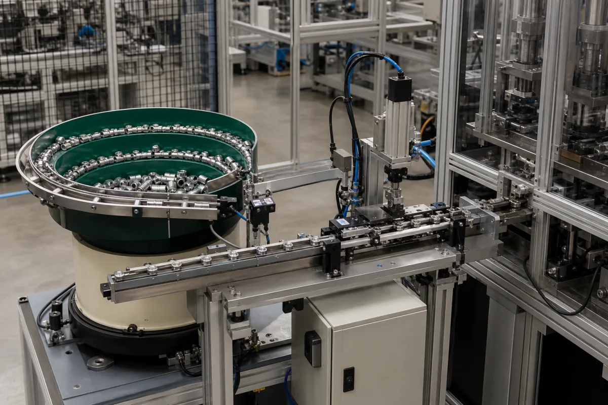
Feeding mechanism between bowl feeder and assembly: the linear track, the track-full sensor and the escapement that hands over one part at a time
The feeding mechanism after the bowl · A tooled linear track that queues oriented parts, a high-level sensor that stops the bowl when the track is full, and an escapement or nest that singulates one or two parts for the robot or pick-and-place
This page covers the feeding mechanism between a vibratory bowl feeder and the machine it serves: the tooled linear track that carries oriented parts in single file, the sensors that keep it filled without overloading, and the escapement or nest that separates one part from the line and presents it at the pick position. Ask three things first: how long a queue the track must hold and at what rate, how track-full and part-present are sensed and what they switch, and which escapement presents parts to your gripper and how many at a time.
Linear tracks, track sensing and part escapements or nests that take oriented parts from a feeder to a pick position. Vibratory bowl feeders with their drives and tooling are covered on the Vibratory bowl feeder page, the choice between bowl and flexible feeding on the Feeding systems page, camera checks at the track on the Vision sensing module for a parts-feeder track page, and terminal insertion supply stations on their own page. Bulk hoppers, step feeders and cartoning machine infeeds are outside this page.
CNFX editorial research · Sources checked October 12, 2026 · 4 sources
The linear track: a queue of oriented parts, kept full but not overloaded
RNA Automation's case studies show the track as a buffer between bowl and escapement: a valve body line with a tooled linear track of about 800 mm and a plunger line with about 400 mm, each with a high-level sensor feeding parts into the escapement for an assembly robot at 5 seconds per assembly; and an M3 × 8 mm screw line with a track of about 250 mm feeding a three-position escapement at 20 parts per minute. [2][3] An Augat patent on a contact insertion machine places a detector, a light source and photodetector, at the top of the track near where it meets the feeder slot, so that when the track is filled the interrupted beam turns off the bowl feeder until the last part moves down toward the escapement, preventing overloading and jamming at the escapement; as an alternative it names a spillback system in which parts fall back into the feeder when track and slot are full. [4]
Editorial calculation: at 20 parts per minute the escapement takes a part every 3 seconds, so the queue on the track is what keeps the robot supplied while the bowl restarts after a track-full stop; ask the supplier how many parts the track holds and how long the bowl takes to refill it.
Give the supplier part drawings and samples, the orientation required at pick, rate per minute, the pick method (robot, pick-and-place, manual), the number of parts per pick, the space between bowl and machine, and the control interface for sensors and escapement.
02
Escapements and nests: separating one part from the line and presenting it for pickup
RNA Automation describes escapements and nests as devices that separate one part from the line leaving a linear feeder or conveyor and release it, correctly oriented, at the right place for manual or automated handling. A static or dead nest presents the part at a fixed pickup point and the next part fills the vacancy as soon as one is removed; pneumatic escapements singulate with actuators and confirm part presence at the pick position with sensors, in forms including blow feed, tic-toc mechanisms, side shuttles and rotary actuators, with optional vision orientation checks; electric escapements can present parts in multiples through multi-pocket side shuttles or rotary actuators; rotary tables index parts round to pick positions. RNA tests each escapement with the full feed system and supplies it with leads looped, wired to a junction box, or under a full PLC control. [1]
Explore company information and manufacturing capabilities, then discuss the scope of your project with a relevant supplier.
Share this page
Compiled and source-reviewed by the CNFX editorial team.
Each manufacturer above links to the page on that company's own website where the product is listed, with the date we checked it. How we source and review
· Page last updated 13 October 2026
Buyer questions
How does a bowl feeder know when the track is full?
An Augat patent uses a light beam across the top of the track: when parts block it, the bowl feeder stops until the queue moves down; RNA fits high-level sensors on its linear tracks. [4][2]
What is a part escapement?
RNA describes it as a device that separates one part from the line leaving a linear feeder and presents it, oriented, at the pick position, using nests, pneumatic or electric shuttles, or rotary tables. [1]
Can an escapement present more than one part at a time?
Yes: RNA's screw line uses a three-position side shuttle that presents two parts at a time from alternate sides of the track. [3]
Sources and what still needs a direct check
Sources checked 2026-10-12. RNA Automation describes its own escapements and feed systems; an Augat patent describes track-full sensing on a bowl-fed insertion machine.