Editorial Technical Reference

Flow Distribution Manifold

This page explains how Flow Distribution Manifold is classified within Machinery and Equipment Manufacturing. Technical values and manufacturer relationships are research references; confirm the current specification and supplier evidence for each order.

Technical Definition & Core Assembly

A component that evenly distributes fluid flow to multiple outlets within an in-line separation system.
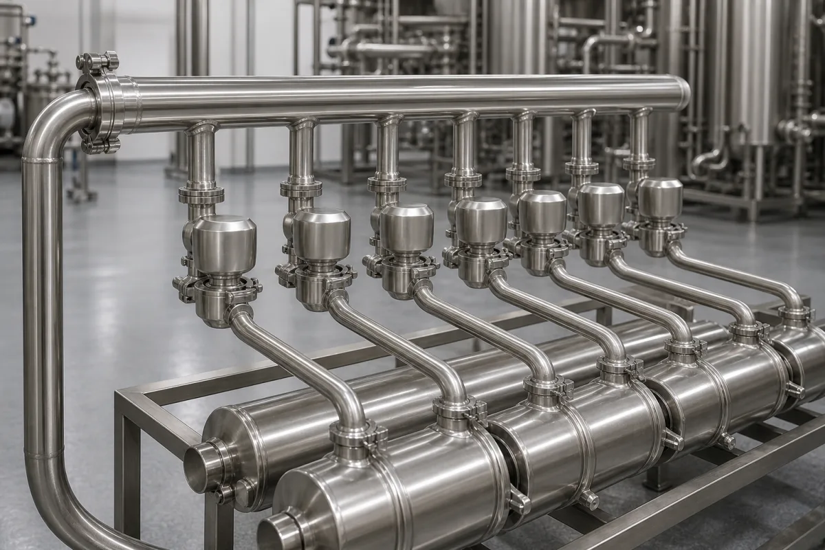
Representative product image. Confirm appearance and specifications with the manufacturer.

Product Specifications

Technical details and manufacturing context for Flow Distribution Manifold

Definition
The Flow Distribution Manifold is a critical component of the In-line Separation Unit that receives incoming fluid from a single source and distributes it evenly to multiple separation chambers or processing lines. It ensures uniform flow rates and pressure across all outlets, which is essential for maintaining separation efficiency and preventing channeling or uneven processing. The manifold operates by using internal channels, baffles, or flow dividers to split the incoming fluid stream into multiple equal streams. The design minimizes pressure drops and turbulence while maintaining consistent flow characteristics to all connected separation elements. Typical configurations include nominal diameters from DN25 to DN100 (ISO 6708), with 2 to 8 outlets. Operating pressure ranges from 1.0 to 1.6 MPa, and operating temperature from -20°C to 120°C. Flow rate capacity is 5 to 50 m³/h, with a maximum pressure drop of 0.05 MPa. Flow distribution accuracy is ±5%. Body materials include 304/316L stainless steel (ASTM A240), with seal materials EPDM or FKM (ASTM D2000). Connection types are flanged or threaded (ISO 7005). Weight ranges from 5 to 30 kg, and surface finish is Ra ≤ 0.8 μm (ISO 4287). Materials on file include Stainless Steel 316L, Duplex Stainless Steel, and Hastelloy. These values are reference ranges; actual specifications must be confirmed with the manufacturer for the specific model and application. The manifold is designed for use in in-line separation systems, ensuring even distribution to maintain process efficiency. It is not a standalone product but a component integrated into a larger system. Proper selection requires consideration of fluid properties, flow rate, pressure, temperature, and compatibility with process media. Verification of performance and compliance with applicable standards should be conducted with the legal manufacturer or supplier.
Working Principle
The manifold operates by using internal channels, baffles, or flow dividers to split the incoming fluid stream into multiple equal streams. The design minimizes pressure drops and turbulence while maintaining consistent flow characteristics to all connected separation elements. This ensures that each outlet receives the same flow rate and pressure, which is critical for uniform processing and preventing channeling or uneven distribution. The internal geometry is engineered to balance flow paths, often incorporating symmetrical layouts and flow conditioning features. The result is a reliable and predictable distribution of fluid, essential for the efficiency of the separation process.
Common Materials
Stainless Steel 316L, Duplex Stainless Steel, Hastelloy
Technical Parameters
ParameterTypical rangeNotes & selection driver
Nominal DiameterDN25–DN100 mmDetermines flow capacity and connection size.ISO 6708
Number of Outlets2–8Even distribution across all outlets.
Operating Temperature-20–120 °CSeals degrade above 120°C.
Flow Rate5–50 m³/hMax flow for even distribution.
Pressure Drop≤0.05 MPaHigher drop indicates poor distribution.
Flow Distribution Accuracy±5 %Deviation from equal flow per outlet.
Body Material304/316L316L for corrosive media.ASTM A240
Seal MaterialEPDM/FKMFKM for high temperature.ASTM D2000
Connection TypeFlanged/ThreadedFlanged for high pressure.ISO 7005
Weight5–30 kgDepends on size and material.
Surface FinishRa ≤ 0.8 μmSmooth finish reduces fouling.ISO 4287

Ranges are indicative industry figures for RFQ preparation, not a supplier commitment. Confirm every value and standard with the legal manufacturer before ordering.

Components / BOM
  • Inlet Port Part
    Receives incoming fluid from the main pipeline
    Material: Stainless Steel
  • Distribution Chamber
    Internal volume where fluid is divided into multiple streams
    Material: Stainless Steel
  • Outlet Ports Part
    Deliver equal flow to separation chambers
    Material: Stainless Steel
  • Flow Equalization Baffles Part
    Ensure uniform flow distribution across all outlets
    Material: Stainless Steel

Applied To / Applications

This component is essential for the following industrial systems and equipment:

Industrial Ecosystem & Supply Chain Structure

Complementary Systems
Downstream Applications
Specialized Tooling

Application Fit & Sizing Matrix

Operational Limits
pressure: Up to 10 bar (150 psi)
flow rate: 0.5 to 50 m³/h per outlet
temperature: -20°C to 150°C
slurry concentration: Up to 30% solids by weight
Media Compatibility
✓ Water-based fluids ✓ Hydrocarbon liquids ✓ Chemical process streams
Unsuitable: Highly abrasive slurries with sharp particles
Sizing Data Required
  • Total system flow rate (m³/h)
  • Number of outlet ports required
  • Required pressure drop across manifold

Reliability & Engineering Risk Analysis

Failure Mode & Root Cause
Abrasive erosion
Cause: High-velocity flow carrying particulate matter causing material wear at bends and restrictions
Cavitation
Cause: Pressure drops below vapor pressure at flow restrictions, leading to bubble formation and implosion damage
Maintenance Indicators
  • Visible external leaks or weeping at flange connections
  • Audible hammering or vibration indicating flow instability or cavitation
Engineering Tips
  • Install strategically placed pressure gauges to monitor pressure drops across sections and identify developing restrictions
  • Implement regular ultrasonic thickness testing at high-wear areas to detect erosion before failure occurs

Indicative industry ranges for design and RFQ preparation. Confirm the exact figures and applicable standard with the manufacturer before specifying.

Compliance & Manufacturing Standards

Applicable Standards
ASME B31.3 - Process Piping DIN EN 1092-1 - Flanges and their joints

Quoted from the published standard.

Manufacturing Precision
  • Bore diameter: +/-0.02mm
  • Surface flatness: 0.1mm per meter
Quality Inspection
  • Hydrostatic pressure test
  • Dimensional verification with CMM

Manufacturers of Flow Distribution Manifold

Manufacturer profiles associated with Flow Distribution Manifold.

Sourcing Flow Distribution Manifold from China?
Tell us your specification and target quantity — we will match it against manufacturer records and come back with the factories that fit.
Request manufacturers We manufacture this

Manufacturer listings support early research and capability understanding. They are not certification, ranking, or transaction guarantees.

Technical documentation
Request current drawings, revision history, and a signed specification sheet.
Manufacturing capability
Verify equipment lists, process limits, capacity, and representative production evidence.
Inspection readiness
Confirm test methods, calibrated equipment, sampling plans, and traceable reports.
Supplier transparency
Check the legal entity, factory address, ownership, certifications, and direct contacts.

CNFX does not score or rank suppliers. Buyers must verify all claims and documents with the legal manufacturer before ordering.

Supply Chain Compatible Machinery & Devices

Hydraulic Press

Industrial machine using hydraulic pressure to compress, form, or assemble materials

Explore Specs →
Heavy-Duty CNC Plasma Cutting Machine

The Heavy-Duty CNC Plasma Cutting Machine is a standalone industrial device designed for cutting conductive metals such as steel, stainless steel, aluminum, and copper alloys.

Explore Specs →
Automated Powder Coating System

Integrated industrial system for applying dry powder coatings to metal substrates.

Explore Specs →
Centrifugal Pump Impeller

The centrifugal pump impeller is a critical rotating component that converts mechanical energy from the motor into kinetic energy in fluid systems.

Explore Specs →

Frequently Asked Questions

What is the purpose of a flow distribution manifold?

It evenly distributes incoming fluid from a single source to multiple outlets, ensuring uniform flow rates and pressure across all separation chambers or processing lines, which is essential for maintaining separation efficiency.

What are the typical operating parameters?

Reference ranges include nominal diameter DN25-DN100, 2-8 outlets, operating pressure 1.0-1.6 MPa, temperature -20 to 120°C, flow rate 5-50 m³/h, and pressure drop ≤0.05 MPa. These are directory references and must be confirmed for the specific model.

Which materials are available?

Body materials include 304/316L stainless steel (ASTM A240), and seal materials EPDM or FKM (ASTM D2000). Other materials on file include Stainless Steel 316L, Duplex Stainless Steel, and Hastelloy. Confirm material suitability with the manufacturer.

How do I verify the manifold's performance?

Check the flow distribution accuracy (±5%) and pressure drop (≤0.05 MPa) against your process requirements. Always verify model-specific values and standards with the legal manufacturer or supplier before procurement.

Data Basis

Editorial classification, named public sources where available, and source-reviewed manufacturer records.

Preliminary Technical Classification
This page supports structured research, RFQ preparation, and supplier evaluation. It does not replace buyer-led supplier qualification, standards review, or technical approval.
Buyer enquiry

Request manufacturing insight for Flow Distribution Manifold

Ask for use case, specification boundaries, supplier type, and RFQ preparation information for this product.

Where it goes
Straight to the CNFX editorial desk, and to the manufacturer if this product is linked to a claimed profile. Nothing is broadcast to a supplier list.
Your details stay here
We do not sell or rent enquiry data, and we do not add you to a mailing list. Used only to answer this request.
No commission, no middleman
CNFX is a directory. We take no cut of any order and never negotiate on a supplier's behalf.
What we don't claim
A listing is not an endorsement. Qualify every supplier and verify every figure yourself before ordering.

Your business information is used only to process this request.

Thank you! Your message has been sent. We'll respond within 1–3 business days.
Sorry, we couldn't send your message. Please try again, or email us at contact@cnfx.com.

Need to Manufacture Flow Distribution Manifold?

Compare manufacturer profiles with relevant product and process capability.

Previous Product
Z-axis Ram/Spindle
Last Product
Get QuotesChat