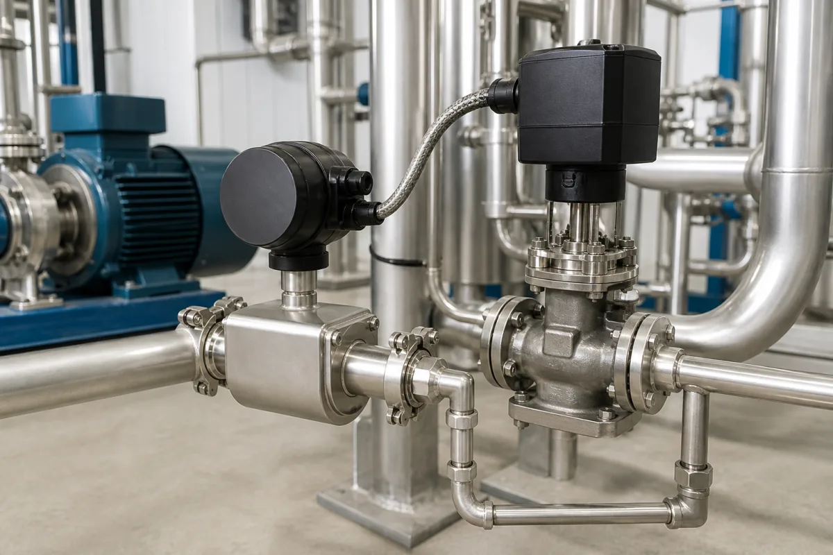
Liquid flow controller with electric valve actuator for pumped process and cooling lines
Liquid flow control on pumped lines with an electric valve actuator: modulating duty and starts per hour, deadband and response time, and the paddle flow controller that trips on low flow
On a pumped liquid line, flow control means a flow signal, a controller with a set point, and an electrically driven valve that moves in small steps all day. The electric actuator has to be rated for that modulating duty, which makers state as a separate duty class and a maximum number of starts per hour from open-close actuators. The second kind of flow controller on the same skid is simpler: a paddle unit that switches a contact when cooling flow drops below a set value.
Closed-loop flow control of liquids in pumped process, cooling-water and utility lines using an electric (motor-driven) valve actuator, its positioner or servo amplifier and a 4–20 mA flow signal, together with paddle-type flow controllers that switch a contact at a set flow. Thermal, laminar and Coriolis mass flow controllers for gases are covered on the Mass flow controller (MFC) page; flow meters themselves on the Flow meter page; pneumatic globe control valves, their sizing and trim on the Pneumatic globe control valve page; and pneumatic micro-flow valves on the Low-flow pneumatic flow control valve page. Pneumatic speed controllers for air cylinders are outside this page.
CNFX editorial research · Sources checked October 12, 2026 · 5 sources
Open-close or modulating: the duty class and starts per hour of the electric actuator
AUMA rates its SA multi-turn actuators for open-close duty as short-time duty S2 – 15 min, and its SAR actuators for modulating duty as S4 – 25%, with a maximum of 1,200 starts per hour for motors up to 0.55 kW, a torque range of 30 to 1,000 Nm and a modulating torque range of 20 to 500 Nm. [1]
Its variable-speed SARV models are rated for modulating duty (class C) S4 – 25%, with S4 – 50% as a special version, a maximum of 1,500 starts per hour, output speeds of 6 to 240 rpm and a speed control ratio of 1:10. [2] Editorial calculation: 1,200 starts per hour is one start every 3,600 ÷ 1,200 = 3 seconds, and 1,500 starts per hour one every 2.4 seconds. A flow loop that asks for more corrections per hour than the rating needs a deadband in the controller or a different actuator.
Emerson's Control Valve Handbook notes that electric actuators were traditionally limited to on/off service, that some are now capable of continuous control, and that brushless motors can reduce or eliminate the motor burnout that comes from switching the motor on and off rapidly. It names sites without instrument air, or with too few valves to justify a compressor, as the main use of electric actuation. [3]
Name the duty on the enquiry: modulating (class C, S4) or open-close (S2), the starts per hour the loop will demand, and the torque or thrust at the valve's worst-case differential pressure.
02
Deadband, dead time and the 4–20 mA position loop
Emerson's handbook says a well-engineered valve should respond to signals of 1% or less to reduce process variability. It reports a plant audit in which 30% of valves had deadbands above 4% and over 65% of loops had deadbands above 2%. [3]
Response is measured as T63, the time from the signal change until the valve reaches 63% of the change, made up of dead time and dynamic time. The handbook prints a specification of 0.2 s dead time and 0.6 s T63 for a 4-inch valve, and recommends that dead time be no more than one-third of the overall response time; in a fast loop, where the process time constant approaches the valve dead time, that dead time dominates loop performance. [3]
On the electric side, the DKJ angular-travel actuators sold by Shanghai Automation Instrumentation take a 4–20 mA DC (or 0–10 mA) command, turn the output shaft through 0 to 90°, return a 4–20 mA position signal and list a conversion error and long-term stability of no more than ±0.1% FS each, on 220 V AC ±20% and at −40 to 75 °C ambient. [4] Editorial note: the actuator's ±0.1% figure is a position-transmitter value; the deadband of the whole valve assembly under flowing conditions is what Emerson's 1% guidance refers to, so ask for a step test of the assembled valve.
03
Paddle flow controller: a set-point contact for low cooling flow
The other device sold as a flow controller does not modulate. Shanghai Automation's LKB-01, made by Shanghai Far East Instrumentation Factory, is a flow controller with a sensor and an adjustable set value for water cooling systems and other fluid circuits; it switches one changeover contact. [5]
Editorial note: a paddle unit with a contact protects equipment on loss of flow (a pump trip, a closed valve, a blocked strainer) but does not measure the flow value, so a modulating loop still needs its own flow transmitter. The 3 A resistive contact rating is lower for inductive loads such as contactor coils; confirm the rating for the actual load. Fit it with the arrow on the housing in the flow direction, as the maker instructs. [5]
Paste it into your enquiry below or into an email to a maker, then replace every bracket.
Liquid: [name; temperature; viscosity; solids]
Flow: [minimum, normal, maximum; set point range]
Line: [pipe size; pressure rating; pressure drop available across the valve]
Flow signal: [meter type; 4–20 mA or pulse; range]
Valve and actuator: [valve type; torque or thrust; modulating S4 or open-close S2; starts per hour; stroke time]
Control: [controller location; fail position on power loss; position feedback]
Low-flow trip: [set point; contact rating and load; pipe size; straight run available]
Power and site: [supply voltage; ambient temperature; enclosure; hazardous area]
1 company lists this product among what they make. Company figures are quoted from each
company's own website; every card states where the relationship came from.
Shanghai Automation Instrumentation Co., Ltd
Manufacturing site to be confirmed for the order
Sells the LKB-01 and LKB-02 flow controllers (set-point contact units for water cooling and other fluid circuits) and DKJ angular-travel electric actuators with 4–20 mA command and position feedback for valves and dampers.
Product scope checked 2026-10-12
Own website lists LKB flow controllers and DKJ electric actuators · profile compiled by CNFX from public sources
Explore company information and manufacturing capabilities, then discuss the scope of your project with a relevant supplier.
Share this page
Compiled and source-reviewed by the CNFX editorial team.
Each manufacturer above links to the page on that company's own website where the product is listed, with the date we checked it. How we source and review
· Page last updated 13 October 2026
Buyer questions
Can an open-close electric actuator be used for flow control?
AUMA rates its open-close SA units for S2 – 15 min short-time duty and its modulating SAR units for S4 – 25% with up to 1,200 starts per hour, so a modulating flow loop needs the modulating version. [1]
How small a signal change should a flow control valve follow?
Emerson's handbook says a well-engineered valve should respond to signals of 1% or less, and reports an audit where 30% of valves had deadband above 4%. [3]
What does a paddle flow controller need on installation?
For the LKB-01, 10 pipe diameters of straight pipe upstream, the arrow in the flow direction, and a medium at 5 to 80 °C within 1.6 MPa. [5]
Sources and what still needs a direct check
Sources checked 2026-10-12. Duty classes and starts per hour are AUMA's for its SA/SAR ranges; deadband and response figures are from Emerson's Fisher handbook; DKJ and LKB data are from Shanghai Automation Instrumentation's product pages.