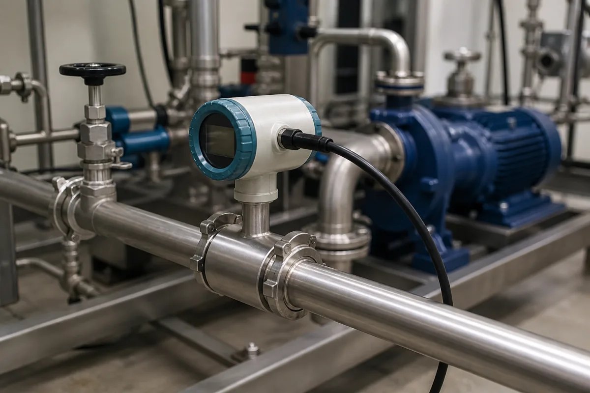
Flow sensor for liquid fertilizer injection (fertigation dosing feedback)
Fertilizer injection flow sensors · millilitre-per-minute ranges on the fertilizer branch, paddlewheel versus ultrasonic sensing, chemical calibration, pulse and 4–20 mA feedback to the dosing controller
In a fertigation system the main irrigation meter measures water by the cubic metre per hour, while in one published system the fertilizer side is a Venturi rated at 150 L/h of suction. The flow sensor on each fertilizer branch tells the controller how much concentrate is actually going in, so it can adjust the injection pump or valve and keep the water-to-fertilizer ratio on target. Ask three things first: what range of concentrate flow each branch carries, which sensing principle works at that flow with your fertilizer solution, and what signal the dosing controller needs.
Flow sensors for fertilizer concentrate and other chemical feed lines in fertigation and chemical injection: low-range paddlewheel, ultrasonic, impeller (Hall-effect) and gear-type sensors with pulse or analogue outputs. Inline, insertion and clamp-on meters for water, process liquids, gases and steam, including irrigation main-line meters, are covered on the Flow meter page. Air-mass sensors for engines and gas flow sensors are outside this page.
CNFX editorial research · Sources checked October 12, 2026 · 3 sources
Size the sensor for the fertilizer branch, not the irrigation main
A 2025 PLoS ONE study of an integrated water-and-fertilizer irrigation system describes a fertilization pump linked to a flow meter that tracks the liquid fertilizer supplied and estimates what remains in the tank; its controller takes the preset fertilization flow as the target and the measured flow as feedback, and corrects deviations by changing the frequency of the hose pump's converter. Flow sensors monitored both main and branch flows, with readings logged over Modbus RTU at a sampling interval of 11.8 s and the water-fertilizer ratio adjusted every 5 s. [1]
The same study pairs an electromagnetic main-line flow meter with a 4–20 mA output, a 0–70 m³/h range and 0.5% accuracy with a Venturi rated at 150 L/h of fertilizer suction and accommodating four suction channels, and prepared a urea stock solution at 110 g/L; the authors state that the precision of the flow sensor has a marked effect on how far the water-fertilizer ratio fluctuates. [1]
Editorial calculation: the Venturi's full 150 L/h is 2.5 L/min, or about 0.2% of the 70 m³/h full scale of that main-line meter (0.15 ÷ 70), and each of its four channels can carry less. A fertilizer line therefore needs its own sensor whose range is built around litres or millilitres per minute; in the same system the main meter measures the water side.
Give the supplier the fertilizer or chemical and its concentration, the minimum and maximum flow on each injection branch, line size and connection, pressure and temperature at the sensor, the controller input (pulse, 4–20 mA or Modbus), and whether the sensor must also trigger batch totals or alarms.
02
Pick paddlewheel or ultrasonic sensing for the concentrate flow
Blue-White's MICRO-FLO is a digital paddlewheel flow sensor for 30 to 7,000 mL/min (0.008–1.85 GPM) in 1/8, 1/4 or 1/2 in NPT or tubing connections, with PVC, PVDF or polypropylene bodies, rated 150 psig (10 bar) at 70 °F and 200 °F (93 °C) at 0 psi. It reads the paddle with an infra-red light beam, needs 9–28 V DC, gives a 5 V DC square-wave output in its sensor-only version, and states full-scale accuracy of ±6%. [2]
Blue-White's MS6 Sonic-Pro chemical feed meter measures 10–5,000 mL/min or 100–10,000 mL/min ultrasonically with PVDF and PEEK wetted parts and 1/2 in connections, rated 200 psi with an operating temperature of 14–104 °F (−10 to 40 °C). It ships pre-calibrated for water, aqueous ammonia 10%, ammonium hydroxide 30%, ammonium sulfate 10%, ferric chloride 40%, sodium hypochlorite 12.5%, sodium permanganate 40% and hydrofluorosilicic acid 25%, with custom calibration for others; it provides an isolated 4–20 mA output, a 0–1,000 Hz pulse output and a solid-state relay that can trigger on flow rate or on totals for batch and proportional feed, with selectable 1–32 s averaging, a NEMA 4X (IP66) enclosure and a 5 V DC, 5 W supply. [3]
Editorial calculation: ±6% of a 7,000 mL/min full scale is ±420 mL/min, which is ±16.8% of a 2,500 mL/min reading (the full 150 L/h Venturi rating) and ±42% of a 1,000 mL/min reading; full-scale accuracy loosens in proportion as the flow falls, so match the sensor's full scale closely to the branch flow. [2] Ask whether the stated accuracy applies to your fertilizer solution or only to water, since the ultrasonic meter's chemical calibrations show that the fluid matters. [3]
03
Low-flow sensors with published figures
Sensor
Range and signal
Source
Paddlewheel, infra-red pickup (MICRO-FLO)
30–7,000 mL/min; 5 V square wave; ±6% full scale. [2]
Explore company information and manufacturing capabilities, then discuss the scope of your project with a relevant supplier.
Share this page
Compiled and source-reviewed by the CNFX editorial team.
Each manufacturer above links to the page on that company's own website where the product is listed, with the date we checked it. How we source and review
· Page last updated 13 October 2026
Buyer questions
Why not use the irrigation main meter to measure fertilizer?
In one PLoS ONE system the main meter spans 0–70 m³/h, while its Venturi fertilizer injector is rated at 150 L/h, about 0.2% of that full scale (editorial calculation). [1]
What flow range do fertilizer injection sensors cover?
Blue-White lists 30–7,000 mL/min for a paddlewheel sensor and 10–10,000 mL/min in two ranges for an ultrasonic chemical feed meter. [2][3]
What signal does a dosing controller get from the sensor?
The ultrasonic meter offers 4–20 mA, 0–1,000 Hz pulse and a relay; the paddlewheel sensor gives a 5 V square wave. [3][2]
Sources and what still needs a direct check
Sources checked 2026-10-12. The PLoS ONE paper reports a research fertigation control system; Blue-White describes its own chemical feed flow sensors.