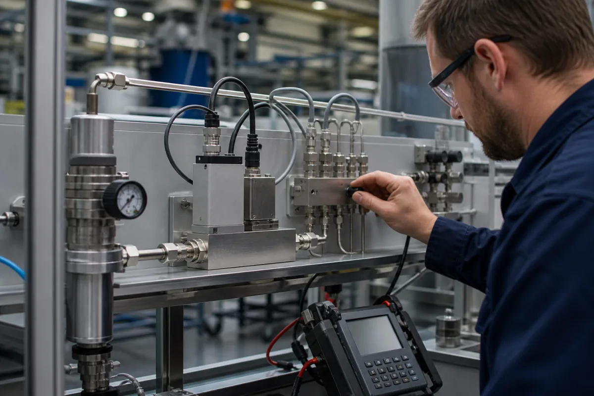
Precision flow controller of the pressure-based type: gas flow computed from the pressures across a restrictor or orifice, for vacuum process tools
Pressure-based, pressure-insensitive gas flow controllers for semiconductor gas boxes · flow computed from P1, P2 and temperature across a restrictor or orifice, critical ratio about 0.5, inlet windows of 110 to 750 kPa(A), down to 0.025 sccm
A pressure-based flow controller has no heated sensor tube. It reads the gas pressure before and after a fixed restriction, plus the gas temperature, calculates the flow from those three values, and moves a fast piezo or solenoid valve until the calculated flow equals the set point. Because the downstream side of an etch or deposition chamber sits at vacuum, an orifice can be run in the critical region, where flow depends on upstream pressure alone. Buying one means matching the supply pressure, the chamber pressure and the flow range to the controller's pressure windows, and checking how accuracy is stated at the low end.
Pressure-based (pressure-type) mass flow controllers and pressure-insensitive mass flow modules for gases: flow restrictor and critical-orifice designs that compute flow from upstream and downstream pressure and temperature, as used in semiconductor and other vacuum process gas systems. Thermal, laminar differential-pressure and Coriolis mass flow controllers chosen by sensing principle, accuracy and turndown for general gas service are covered on the Mass flow controller (MFC) page; closed-loop liquid flow control in pumped lines with electric valve actuators on the Liquid flow controller with electric valve actuator page; flow meters on the Flow meter page. Complete gas panels and pressure regulators are outside this page.
CNFX editorial research · Sources checked October 12, 2026 · 6 sources
Flow from two pressures and a temperature: the critical ratio of about 0.5 and what happens above it
Fujikin and Tokyo Electron's patent on a pressure-type flow rate control apparatus states the physics directly. Gas passing an orifice from upstream pressure P1 to downstream pressure P2 (both absolute) follows Q = S·C·P1/T^½ once it reaches sonic velocity, where S is the orifice area and T the gas temperature, so flow then depends on P1 alone; below sonic velocity the flow also depends on P2. The critical ratio rc is 0.53 for diatomic gases such as O2 and H2 and 0.54 for nonlinear triatomic gases, about 0.5 in both cases. [1]
The same patent lists the drawbacks its inventors saw in conventional mass flow controllers: relatively slow response, poor flow accuracy at low flow rates, operational difficulties and high cost. To keep control accurate when P2/P1 rises above the critical value, it fits an empirical sub-sonic formula Qc = K·P2^m·(P1 − P2)^n with 0.40 < m < 0.50 and 0.50 < n < 0.65 (m = 0.47152 and n = 0.59492 for a 0 to 10 sccm range), and switches between the two formulas by continuously comparing the measured pressure ratio with rc. [1]
HORIBA describes its CRITERION D500 series differently: a pressure sensor on the supply, a gas filter, a piezo-actuated control valve, two pressure sensors either side of a laminar-flow-element restrictor, and a temperature sensor, with flow calculated from the two pressures and the gas temperature. Its restrictor follows Flow = k(P1² − P2²) when the downstream pressure is reduced, and because the differential pressure rises more steeply at low flow, the low-flow region is read with better resolution, which HORIBA gives as the reason one unit can control from 100% down to 0.2% of full scale. Flow-rate properties measured on actual process gases are stored in the controller to support ±1% of set point accuracy on those gases. [2]
HORIBA also states that its pressure-control MFCs achieved faster response and better accuracy than conventional thermal-control MFCs, and that the D500 series has been used mainly in etching equipment, with nickel and cobalt-nickel alloys on the pressure sensor and valve of the D507 version for gases such as HF and F2 used in diffusion tool cleaning. [2]
Give the supplier the gas, its full-scale flow, the supply pressure range and the downstream chamber pressure during the process step, so it can confirm whether the unit runs in the critical region or relies on its sub-sonic model.
02
Inlet 110 to 750 kPa(A), downstream at most 13.3 or 53.3 kPa(A): reading a D500 specification
HORIBA's D500 product specification shows how tightly a pressure-based unit ties flow range to pressure. The H range covers 100 sccm to 10 slm full scale with an operating inlet pressure of 350 to 750 kPa(A) and at least 350 kPa differential; the M range, 50 sccm to 5 slm, needs 240 to 450 kPa(A) and at least 240 kPa; the L range, 10 sccm to 1 slm, works from 110 to 350 kPa(A) with at least 110 kPa. Each range is specified at a downstream pressure of at most 13.3 kPa(A) or at most 53.3 kPa(A). [3]
Accuracy is quoted in two parts. In the first column of the table (read here as the H range at up to 13.3 kPa(A) downstream), flow accuracy at 25 °C is ±1% of set point from 5 to 100% of full scale and ±0.05% of full scale from 0.2 to 5%, with repeatability of ±0.3% of set point and ±0.015% of full scale over the same bands; the last column reads ±1% of full scale from 5 to 100%. Temperature error is ±0.05% of set point per °C in the upper band. Offset and span stability are listed as ±0.5%, ±1% and ±5% of full scale per year across the columns. [3]
Editorial calculation: on a 10 slm unit, 5% of full scale is 500 sccm; ±1% of that set point is ±5 sccm, and ±0.05% of full scale is also ±5 sccm, so the two forms meet at the 5% boundary. At a 100 sccm set point (1% of full scale) the ±5 sccm band is ±5% of the reading. [3]
Other D500 figures: normally closed piezo actuator valve; settling time for a step up of at most 0.8 s (1 s in one column) on N2 per SEMI E17-1011; valve seat leak below 0.2%, 0.5% or 2% of full scale; proof pressure 1,000 kPa(A); helium leak integrity of at most 5 × 10⁻¹² Pa·m³/s; wetted parts in 316L stainless steel and nickel alloy; 1/4-inch VCR-equivalent or 1.125-inch IGS fittings; operating temperature 15 to 45 °C; warm-up of at least 30 minutes; and a ±15 V supply drawing at most 200 mA and 150 mA. [3]
Editorial calculation: with the H range at its lowest inlet of 350 kPa(A) and the chamber at 13.3 kPa(A), P2/P1 = 13.3 / 350 ≈ 0.04, far below the critical ratio of about 0.5 that the Fujikin patent gives for an orifice; at 53.3 kPa(A) downstream and the L range's 110 kPa(A) minimum inlet, the ratio is about 0.48, close to it. [3][1]
Check that the lowest supply pressure your gas line can deliver, minus any filter and valve drop, still sits inside the controller's inlet window, and state the highest chamber pressure in any process step.
03
Checking the controller in place: restrictor self-tests, failure flags and the pressure-rate limit
HORIBA lists a G-LIFE (Gas Law check of Integrated Flow restrictor Equation) self-diagnosis on the D500 that lets operators run their own tests, alongside a response of less than 0.8 s and a control range of 0.2 to 100% of full scale. [4]
The later D700T adds failure detection for pressure sensor shift, valve seat leak and flow accuracy change, with settling time of at most 100 ms set to set, step up and step down, repeatability within 0.15% of set point and best-case accuracy within 0.45% of set point (0.8% standard), accuracy guaranteed down to 0.1 sccm N2 equivalent, and a 15 to 60 °C operating range. Its pressure-insensitive rating holds only while pressure perturbation stays below 20% pressure change per second and ±70 kPa/s (±10 psi/s), and HORIBA notes that zero adjustment is needed after installation to remove orientation influence. [5]
For very small flows, HORIBA's D700uF is aimed at flows of 5 sccm and below, with flow control down to 0.025 sccm, a step-up response of 100 ms or less, a state monitor function, and a PFA nozzle for valve shut-off and corrosion resistance; the same 0.1 sccm N2-equivalent accuracy floor and pressure-perturbation limit are footnoted. [6]
Ask which self-checks run in place, how long each takes, what they flag, and what rate of inlet pressure change the pressure-insensitive rating assumes.
04
Gas, pressure and flow data for a pressure-based flow controller
Paste it into your enquiry below or into an email to a maker, then replace every bracket.
Gas: [species; corrosive or not]
Full scale: [sccm or slm]
Lowest set point: [sccm]
Supply pressure: [min-max kPa(A)]
Downstream pressure: [highest chamber pressure in any step, kPa(A)]
Accuracy: [% S.P. and % F.S. bands needed]
Settling: [ms; step up and step down]
Leak: [He integrity; valve seat leak]
Materials and fittings: [316L, nickel alloy; VCR or IGS]
Interface: [analog; RS-485; DeviceNet; EtherCAT]
Diagnostics: [self-check type and duration]
Explore company information and manufacturing capabilities, then discuss the scope of your project with a relevant supplier.
Share this page
Compiled and source-reviewed by the CNFX editorial team.
Each manufacturer above links to the page on that company's own website where the product is listed, with the date we checked it. How we source and review
· Page last updated 13 October 2026
Buyer questions
How does a pressure-based flow controller measure flow?
It calculates flow from the pressures upstream and downstream of a restrictor or orifice and the gas temperature, then drives a valve to match the set point; under critical conditions orifice flow depends on upstream pressure alone. [1][2]
What is the critical pressure ratio?
The Fujikin and Tokyo Electron patent gives 0.53 for diatomic and 0.54 for nonlinear triatomic gases, about 0.5; below it flow through the orifice is sonic. [1]
What inlet pressure does a pressure-based MFC need?
HORIBA's D500 specifies 350–750 kPa(A) for its H range, 240–450 kPa(A) for M and 110–350 kPa(A) for L, with downstream pressure at most 13.3 or 53.3 kPa(A). [3]
How low can these controllers go?
HORIBA's D700uF is aimed at 5 sccm and below and controls down to 0.025 sccm. [6]
Sources and what still needs a direct check
Sources checked 2026-10-12. The flow equations and critical ratio come from a Fujikin and Tokyo Electron patent; product figures come from HORIBA STEC's D500 specification, its 2017 technical article and its CRITERION product pages.