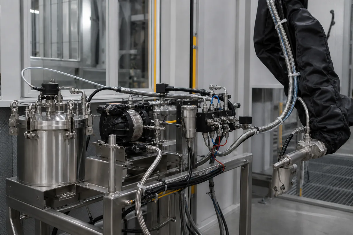
Liquid supply and metering at the robotic applicator
A coating fluid-delivery subsystem connects the material supply to the robot’s applicator and its process controls. Define the circulation loop, metering manifold and robot-side feed separately so a quoted pump or regulator is not mistaken for the complete delivery assembly.
Liquid-coating fluid supply and metering subsystems feeding robotic spray applicators: circulation interfaces, flow-control manifolds, moving feed connections and process-volume verification. Complete coating robots, whole paint kitchens, dry-powder feed/recovery systems and unrelated general-purpose fluid plants are outside this page.
CNFX editorial research · Sources checked October 18, 2026 · 3 sources
Separate circulation pressure from application flow
A paint circulation loop and the final feed to an applicator control different conditions. Graco describes pressure control using transducers at the pump outlet and back-pressure regulator, while its flow mode uses pump volume and piston position to circulate a selected flow. Its hybrid mode operates within pressure and flow windows as viscosity or gun demand changes. That description does not make a pressure reading an independent measurement of nozzle delivery. [1]
Fluid-path boundary
What the source establishes
What to identify in an offered assembly
Circulation pump and return
Graco distinguishes pump control and back-pressure regulation. [1]
Supply/return connections, circulation arrangement and locations of feedback devices.
Applicator feed manifold
Sames lists a flowmeter, air-piloted fluid regulator, atomizing-air regulator and color valves in ColorFlow. [2]
Included fluid versus air components, color-change path and control responsibility.
Robot process control
ABB describes a collected-volume flow test for the installed robot process. [3]
Compatible process controller, applicable test procedure and acceptance specification.
02
Identify the measured variable and the regulated variable
Sames describes closed-loop flow regulation for manual or automatic guns, including compensation for varying back-pressure and automatic priming controlled by volume or time. The presence of a pump, regulator or display alone does not establish that an assembly includes this feedback arrangement. [2]
Request a fluid schematic showing the supply, return, applicator inlet, color valves and cleaning outlets. Mark where flow is measured, where pressure is measured and which actuator changes each variable. Identify whether a quoted flow value is a command, a pump-displacement estimate or a measurement from the supplied meter.
For the robot-mounted part of the assembly, identify the hose routing, moving interfaces and the actual supplied connection points. Obtain the coating-specific wetted-material and cleaning compatibility from the supplier. The hose size, pressure rating and wetted alloy must come from the identified feed assembly’s documentation.
03
Verify collected delivery against the identified process specification
ABB’s PaintControls manual describes a timed material collection and comparison of actual flow with accumulated volume. It ties volumetric accuracy to the gear-pump technical specification. The separate hub-clean flow test instead refers to the actual atomizer specification and its solvent regulator. These are different acceptance references, not a universal accuracy claim for a fluid-delivery subsystem. [3]
Ask the integrator for a commissioning record identifying the coating or test fluid, test conditions, collection interval, commanded delivery and measured result. The robot service procedure includes movement and specified operating modes; its approved procedure and safeguards belong to the installed cell. A setpoint shown on a screen is insufficient evidence of measured application flow.
This page covers liquid-coating supply and metering at a robotic applicator. Dry-powder recovery, cyclone separation and reclaim transfer use a different material path and are outside this scope.
04
Specify the fluid path and control boundary
Paste it into your enquiry below or into an email to a maker, then replace every bracket.
Explore company information and manufacturing capabilities, then discuss the scope of your project with a relevant supplier.
Share this page
Compiled and source-reviewed by the CNFX editorial team.
Each manufacturer above links to the page on that company's own website where the product is listed, with the date we checked it. How we source and review
· Page last updated 18 October 2026
Buyer questions
Does stable circulation pressure prove the applicator flow?
Graco distinguishes circulation pressure and flow control, and Sames describes a dedicated flowmeter and regulating manifold. Identify the actual measurement and control path rather than inferring nozzle delivery from pressure alone. [1][2]
Can one accuracy figure cover paint delivery and atomizer cleaning?
ABB refers the fluid-volume check to the gear-pump specification and the hub-clean check to the actual atomizer specification. Obtain the applicable acceptance limits for each installed circuit. [3]
Sources and evidence scope
Sources checked 2026-10-18. Primary descriptions from Graco, Sames and ABB. Each describes its own control arrangement; these examples do not establish interchangeable components or a universal operating range.