Editorial Technical Reference

Humidity Control System

This page explains how Humidity Control System is classified within Machinery and Equipment Manufacturing. Technical values and manufacturer relationships are research references; confirm the current specification and supplier evidence for each order.

Technical Definition & Core Assembly

A subsystem within an environmental control chamber that regulates and maintains specific humidity levels.
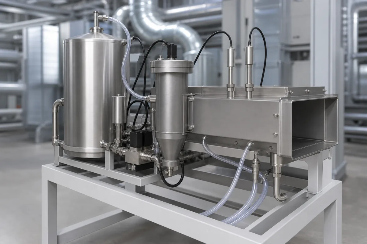
Representative product image. Confirm appearance and specifications with the manufacturer.

Product Specifications

Technical details and manufacturing context for Humidity Control System

Definition
The Humidity Control System is a component of an Environmental Control Chamber, designed to precisely manage moisture content in the air to create and sustain predetermined atmospheric conditions. It operates in conjunction with temperature control systems to simulate various environmental scenarios required for testing, storage, or manufacturing processes. The system typically employs sensors to monitor ambient humidity. Based on setpoint values, it activates humidification elements (e.g. ultrasonic atomizers, steam generators) to add moisture or dehumidification mechanisms (e.g. refrigeration coils, desiccant wheels) to remove moisture from the chamber's air. A control unit processes sensor data and modulates these components to achieve and maintain the target humidity level. The system is constructed with corrosion-resistant materials, including stainless steel for housing and piping, copper for heat exchange coils, electronic components for sensors and controllers, and plastics for insulation and fittings. Key parameters include a humidity control range of 20–95% RH, accuracy of ±1.0% RH at steady state, and control accuracy of ±0.5% RH with a PID controller. The operating temperature range is -40 to 85°C, and the operating pressure is 1.0–1.6 MPa. Power supply is 220–240 V AC (50/60 Hz), with power consumption of 1.5–3.0 kW depending on chamber size. Response time to reach setpoint is ≤60 seconds. The system meets ingress protection ratings of IP54–IP65 per IEC 60529, and the material grade for stainless steel is 304 per ASTM A240. Typical dimensions are 600×800×1200 mm (W×D×H), and weight ranges from 80–150 kg for standard chamber sizes. These values are reference ranges and must be verified for the specific model and application with the legal manufacturer or supplier. The system is designed for integration into environmental chambers, and its performance depends on proper sizing, installation, and maintenance.
Working Principle
The system uses sensors to measure humidity in the chamber air. A control unit compares the measured value to the setpoint. If humidity is below the setpoint, it activates humidification elements such as ultrasonic atomizers or steam generators to add moisture. If humidity is above the setpoint, it activates dehumidification mechanisms like refrigeration coils or desiccant wheels to remove moisture. The control unit modulates these components based on sensor feedback to maintain the target humidity level within specified accuracy.
Common Materials
Stainless Steel (housing, piping), Copper (heat exchange coils), Electronic Components (sensors, controllers), Plastics (insulation, fittings)
Technical Parameters
ParameterTypical rangeNotes & selection driver
Humidity Control Range20–95 % RHTypical range for environmental chambers
Humidity Accuracy±1.0 % RHAt steady state
Temperature Range-40–85 °COperating ambient temperature
Power Supply220–240 V AC50/60 Hz
Power Consumption1.5–3.0 kWDepends on chamber size
Control Accuracy±0.5 % RHWith PID controller
Response Time≤60 sTo reach setpoint
Material304 SSCorrosion-resistantASTM A240
Ingress ProtectionIP54–IP65Dust-tight and water-resistantIEC 60529
Weight80–150 kgFor standard chamber sizes
Dimensions600×800×1200 mmW×D×H for typical unit

Ranges are indicative industry figures for RFQ preparation, not a supplier commitment. Confirm every value and standard with the legal manufacturer before ordering.

Components / BOM
  • Humidity Sensor
    Measures the current relative humidity level within the chamber and sends data to the control unit.
    Material: Electronic components, protective housing
  • Control Unit / PLC
    Processes sensor data, compares it to the setpoint, and sends commands to humidification/dehumidification actuators.
    Material: Electronic circuit boards, plastic/metal enclosure
  • Humidifier
    Adds moisture to the chamber air. Can be ultrasonic, steam, or evaporative type.
    Material: Stainless steel, piezoelectric ceramics (ultrasonic), heating elements
  • Dehumidifier
    Removes moisture from the chamber air. Often uses a refrigeration cycle to condense water vapor or a desiccant material.
    Material: Copper coils (refrigeration), aluminum fins, desiccant rotor, fan
  • Air Circulation Fan
    Ensures uniform distribution of humidified or dehumidified air throughout the chamber to prevent stratification.
    Material: Aluminum/plastic blades, motor housing

Applied To / Applications

This component is essential for the following industrial systems and equipment:

Industrial Ecosystem & Supply Chain Structure

Complementary Systems
Downstream Applications
Specialized Tooling

Application Fit & Sizing Matrix

Operational Limits
pressure: 0 to 1.5 bar
flow rate: 10 to 500 m³/h
temperature: 5°C to 50°C
humidity range: 10% to 95% RH
Media Compatibility
✓ Clean dry air ✓ Nitrogen gas ✓ Process air with low particulate load
Unsuitable: Corrosive gases or environments with high concentrations of oil mist or aggressive chemicals
Sizing Data Required
  • Required humidity setpoint and tolerance
  • Maximum air volume flow rate
  • Ambient temperature range of the installation environment

Reliability & Engineering Risk Analysis

Failure Mode & Root Cause
Condensate Drain Blockage
Cause: Accumulation of mineral deposits, microbial growth (e.g., mold, algae), or debris in drain lines, often due to poor water quality, lack of regular cleaning, or inadequate drain slope.
Humidifier Element Scaling/Corrosion
Cause: Mineral scaling (e.g., calcium, magnesium) on heating elements or electrodes from hard water, or corrosion due to chemical impurities, low pH, or galvanic reactions, leading to reduced efficiency or failure.
Maintenance Indicators
  • Visible water leakage or pooling around the unit, indicating drain blockage, cracked reservoir, or failed seals.
  • Unusual noises (e.g., gurgling, hissing) or inconsistent humidity output, signaling component wear, airflow obstruction, or control system malfunction.
Engineering Tips
  • Implement a water treatment program (e.g., softening, filtration) to reduce mineral content and impurities, preventing scaling and corrosion in humidifier elements and drain systems.
  • Establish a preventive maintenance schedule including regular inspection and cleaning of drains, reservoirs, and sensors, and calibrate humidity controls annually to ensure optimal performance and early fault detection.

Indicative industry ranges for design and RFQ preparation. Confirm the exact figures and applicable standard with the manufacturer before specifying.

Compliance & Manufacturing Standards

Applicable Standards
ISO 14644-1:2015 Cleanrooms and associated controlled environments ANSI/ASHRAE Standard 55-2020 Thermal Environmental Conditions for Human Occupancy DIN EN 15251:2007 Indoor environmental input parameters for design and assessment of energy performance of buildings

Quoted from the published standard.

Manufacturing Precision
  • Humidity sensor accuracy: +/-2% RH
  • Temperature control stability: +/-0.5°C
Quality Inspection
  • Leakage test for ductwork and enclosures
  • Calibration verification of humidity and temperature sensors

Manufacturers of Humidity Control System

Manufacturer profiles associated with Humidity Control System.

Sourcing Humidity Control System from China?
Tell us your specification and target quantity — we will match it against manufacturer records and come back with the factories that fit.
Request manufacturers We manufacture this

Manufacturer listings support early research and capability understanding. They are not certification, ranking, or transaction guarantees.

Technical documentation
Request current drawings, revision history, and a signed specification sheet.
Manufacturing capability
Verify equipment lists, process limits, capacity, and representative production evidence.
Inspection readiness
Confirm test methods, calibrated equipment, sampling plans, and traceable reports.
Supplier transparency
Check the legal entity, factory address, ownership, certifications, and direct contacts.

CNFX does not score or rank suppliers. Buyers must verify all claims and documents with the legal manufacturer before ordering.

Supply Chain Compatible Machinery & Devices

Hydraulic Press

Industrial machine using hydraulic pressure to compress, form, or assemble materials

Explore Specs →
Heavy-Duty CNC Plasma Cutting Machine

The Heavy-Duty CNC Plasma Cutting Machine is a standalone industrial device designed for cutting conductive metals such as steel, stainless steel, aluminum, and copper alloys.

Explore Specs →
Automated Powder Coating System

Integrated industrial system for applying dry powder coatings to metal substrates.

Explore Specs →
Centrifugal Pump Impeller

The centrifugal pump impeller is a critical rotating component that converts mechanical energy from the motor into kinetic energy in fluid systems.

Explore Specs →

Frequently Asked Questions

What is the typical humidity control range?

The typical range is 20–95% RH, but this may vary depending on the specific chamber model and configuration. Always confirm with the manufacturer.

What accuracy can be expected?

At steady state, accuracy is ±1.0% RH. With a PID controller, control accuracy can be ±0.5% RH. These values are reference ranges and should be verified for the actual unit.

What are the power requirements?

The system operates on 220–240 V AC, 50/60 Hz, with power consumption between 1.5 and 3.0 kW depending on chamber size. Confirm the exact requirements with the supplier.

What maintenance is required?

Regular inspection of sensors, cleaning of humidification elements, and checking of dehumidification coils are recommended. Follow the manufacturer's guidelines for maintenance intervals and procedures.

Data Basis

Editorial classification, named public sources where available, and source-reviewed manufacturer records.

Preliminary Technical Classification
This page supports structured research, RFQ preparation, and supplier evaluation. It does not replace buyer-led supplier qualification, standards review, or technical approval.
Buyer enquiry

Request manufacturing insight for Humidity Control System

Ask for use case, specification boundaries, supplier type, and RFQ preparation information for this product.

Where it goes
Straight to the CNFX editorial desk, and to the manufacturer if this product is linked to a claimed profile. Nothing is broadcast to a supplier list.
Your details stay here
We do not sell or rent enquiry data, and we do not add you to a mailing list. Used only to answer this request.
No commission, no middleman
CNFX is a directory. We take no cut of any order and never negotiate on a supplier's behalf.
What we don't claim
A listing is not an endorsement. Qualify every supplier and verify every figure yourself before ordering.

Your business information is used only to process this request.

Thank you! Your message has been sent. We'll respond within 1–3 business days.
Sorry, we couldn't send your message. Please try again, or email us at contact@cnfx.com.

Need to Manufacture Humidity Control System?

Compare manufacturer profiles with relevant product and process capability.

Previous Product
Z-axis Ram/Spindle
Last Product
Get QuotesChat