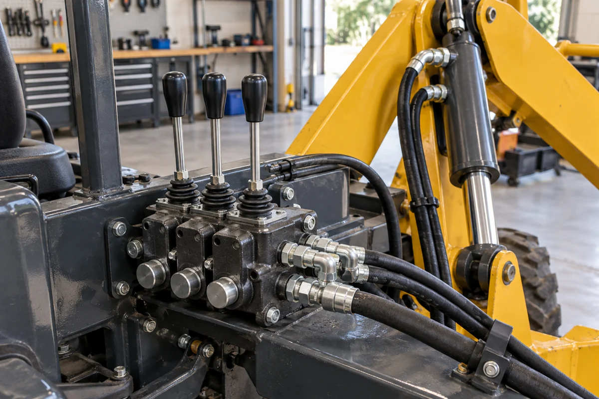
Follow the oil from pump to actuator. Compare sectional, subplate and cartridge constructions, then read the port pressures, spool behaviour and fluid conditions for the valve you actually need.
CNFX editorial research · Sources checked October 9, 2026 · 16 sources
Each family is specified and replaced differently.
Family
Typical use
What decides the order
Mobile sectional directional valve
Mobile equipment such as tractors and mobile cranes; one published valve stacks 1 to 8 work sections [1]
Number of sections, spool function per section, actuation and inlet relief
Subplate-mounted directional valve
ISO 4401:2005 defines mounting-surface dimensions for four-port directional valves. Its public listing remains current, confirmed in 2022. [2]
Match the full mounting code, hydraulic symbol, pressure and flow limits, seals and electrical options. A shared mounting interface alone does not establish functional interchangeability. [5]
Cartridge valve
An individual valve element fitted into a manifold cavity; the Sun screw-in examples include pilot-to-open checks and counterbalance valves with different functions. [6]
Use the exact cavity drawing, port numbering, function and control requirements. A cartridge format does not identify its hydraulic function.
02
The spool changes the oil path through the valve body
This component / BOM reference describes functional parts, not a production bill of materials or a list of interchangeable spares. GRH’s GKV50 sectional valve and Bosch Rexroth’s WE6 solenoid valve are separate constructions. [1][5]
In the open-centre GKV50 arrangement described by GRH, pump oil passes through the neutral passage toward tank while the spools are centred. Moving a work spool closes that neutral path and directs oil from the parallel passage through the section’s load check and bridge passage to work port A or B. The chosen spool symbol determines the complete working and return connections. [1]
That distinction matters when ordering a multi-section bank: the centre condition, each spool function and any power-beyond connection define how the bank feeds the machine. GRH describes power-beyond flow with all spools in neutral; it is a separate connection arrangement, not permission to treat the low-pressure T port as a high-pressure supply. [1]
Component
Role in the valve
Material / construction evidence
Body and oil passages
Locates the moving element and connects the inlet, work and return paths. A sectional bank adds inlet, work and end sections. [1]
GKV50: cast-iron inlet, work and end sections; aluminium spring / detent caps and pilot-module bodies. GRH gives no cast-iron grade.
Spool or poppet
WE6 uses a sliding spool to select connections. A Sun pilot-to-open check uses a seated closing element for its load-holding function; these are not the same component or valve action. [5][6]
The selected documents do not establish a universal internal alloy, hardness or interchangeable replacement spool.
Seals
The seal option must suit the fluid and temperature. It does not eliminate the inherent internal leakage of the WE6 spool construction. [5]
WE6 lists NBR and FKM variants with different temperature limits. The cited sheet does not justify one seal material for every hydraulic fluid.
Return spring or detent
WE6 spring versions return the spool when de-energized; its O version has no return spring, while OF uses a detent. The de-energized state must follow the ordered symbol and option. [5]
Spring and detent material grades are not specified in the cited data. They are alternatives in defined configurations, not mandatory parts with a universal fail position.
Actuator: lever, hydraulic pilot or solenoid
GRH lists manual and hydraulic-remote arrangements; WE6 uses one or two solenoids to move its spool. Electrical options do not apply to a purely manual valve. [1][5]
GRH’s aluminium pilot-module body is a published material detail. Coil winding / encapsulation materials are not established here; specify the actual voltage, connector and actuator assembly.
03
Read a sectional valve datasheet port by port
GRH identifies this example as GKV50. Its named-model table is retained below; these are manufacturer-published values, not independently tested results or limits for the whole hydraulic-valve category. [1]
Pump flow outside the range affects pressure drop and control
Pressure per port
P and A/B ports 350 bar; T (return) port 25 bar [1]
Return-line back pressure must stay below the T rating
Sections and spools
1 to 8 main sections; open-centre 3-position, 4-way spools for double- and single-acting cylinders and motors, float option [1]
Specify the spool function for each section
Actuation
Manual and hydraulic remote are listed. The page also says “wire driving” without defining it. A separate solenoid table gives 12 VDC, 0–1.5 A, or 24 VDC, 0–0.75 A. [1]
Obtain the actuator / pilot module order code and controller requirements. The wording “wire driving” alone does not establish electrical control.
Pressure protection
Inlet section with two-stage or direct-acting relief valve; overload valves on A/B ports; a load check valve in each section [1]
Relief settings are not published, so state them in the order
Materials
Cast-iron inlet, work and end sections; aluminium spring and detent caps and pilot modules [1]
These identify construction materials, not an HT250 grade or a corrosion-resistance rating.
GRH gives 320 bar in its descriptive text and 350 bar in the model table. Its summary metadata also says “Threaded Cartridge”, while the body describes a sectional valve. Resolve these conflicts in the quoted GKV50 configuration sheet; do not silently use the higher pressure or reclassify the product. [1]
04
Read the rating together with the port, seal and electrical option
The WE6 examples below come from Bosch Rexroth RE 23178, edition 2019-01, hosted by Airline Hydraulics. They illustrate a named historical datasheet; they are not a current-stock offer, a replacement approval or extra ratings for GKV50. [5]
Specification field
Documented example
Condition that changes the interpretation
Nominal size / interface
WE6: size 6; mounting pattern ISO 4401-03-02-0-05. [5]
Use the full mounting drawing. A size designation alone is not a measured internal bore diameter or a flow guarantee.
Maximum operating pressure
GKV50 model table: P, A and B 350 bar; T 25 bar. WE6 standard: P/A/B 350 bar, T 210 bar DC or 160 bar AC. [1][5]
Check each port and version. WE6 SO407 has a separate 315 bar P/A/B limit; GKV50’s conflicting general 320 bar statement remains unresolved.
Flow
GKV50: 50 L/min rated, 20 minimum, 60 maximum. WE6 standard maximum: 80 L/min DC or 60 L/min AC. [1][5]
The WE6 sheet also has spool-specific performance-limit curves. Maximum flow is not a promise of any desired pressure drop at that flow.
Internal leakage
GKV50: A/B to T, 25–35 cc/min at 70 bar; 2–5 cc/min with the stated P.O. check option. [1]
Keep the flow path and pressure with the value; the page does not give all viscosity and test details needed for an acceptance test.
Measured without flow at 40 °C and 46 cSt under the sheet’s ISO 6403 test note. These are not loaded-cylinder response times.
Temperature
WE6 standard NBR: ambient −20 to +50 °C; fluid −20 to +80 °C. FKM: ambient −15 to +50 °C; fluid −15 to +80 °C. [5]
Ambient and fluid limits differ. HFC fluids have a separate −20 to +50 °C fluid limit; special low-temperature versions have additional pressure conditions.
Ingress protection
WE6 individual DC connection K4: IP65; K40: IP69K; C4: IP66 in the 2019 table. [5]
The rating requires correct valve mounting and a suitable mating connector. It cannot be assigned to every coil or an unplugged connector.
Coil voltage
WE6 ordering code G24 denotes 24 V DC; its electrical table permits ±10% voltage tolerance. [5]
Select voltage and connection together. GKV50’s separate current ranges do not define WE6 coil requirements.
Electrical power
WE6 standard DC: 30 W; SO407: 8 W; UR version: 34 W. [5]
Do not substitute an option’s power figure for the standard coil. AC holding and inrush are listed in VA, not as this DC wattage.
Body material
GKV50: cast iron, with aluminium caps / pilot bodies as described above. [1]
The source does not identify HT250 or offer 304 stainless steel as an equivalent construction.
Weight
WE6: 1.45 kg with one solenoid; 1.95 kg with two. [5]
These are valve examples from the cited sheet, not the mass of a sectional bank, manifold or complete hydraulic power unit.
05
Separate holding a load from controlling its descent
Internal leakage can contribute to unwanted actuator movement, but a leakage table alone does not diagnose the entire circuit. GRH publishes a particular A/B-to-T test; Sun separately explains why load holding and load lowering need different valve behaviour. [1][6]
Keep the GKV50 leakage result within its test boundary
GRH states 25–35 cc/min from A/B to T at 70 bar, and 2–5 cc/min with its P.O. check option. The reduction is useful model information, but it does not demonstrate zero drift or safe controlled lowering of an arbitrary boom. The publication does not supply a complete leakage acceptance procedure. [1]
A pilot-to-open check releases; a counterbalance valve modulates
Sun describes its pilot-to-open checks as non-modulating valves for holding a load, not controlling actuator speed. A counterbalance valve meters load flow under load and pilot pressure, allowing control of an overrunning load. Sun warns that using a pilot-to-open check for load lowering can produce ratcheting motion. This explains a circuit-function distinction; it is not a claim that a Sun cartridge fits the GRH bank. [6]
Compare the same leakage path and operating state
State the pressure, oil temperature / viscosity, affected ports and whether the measurement is for one section or an assembly. Choose the load-control function from the machine schematic, including pilot and return-pressure conditions, rather than selecting a check option solely because its leakage number is smaller. [1][6]
06
Oil cleanliness is part of the valve specification
ISO 4406:2021 defines the code used to state the quantity of solid particles in a hydraulic fluid [3]. The code has three numbers for particles of 4, 6 and 14 µm and larger per millilitre; each step up roughly doubles the particle count [4].
HYDAC’s columns combine pressure and service conditions: low / medium is below 2000 psi in moderate conditions; high is 2000–2999 psi, or lower-pressure service in severe conditions; very high is 3000 psi and above, or high-pressure service in severe conditions. Its examples of severe conditions include surges, pressure spikes, frequent cold starts and water ingress. [4]
Compare columns side by side. On a narrow screen, scroll the table horizontally.
350 bar is approximately 5,080 psi, within HYDAC’s highest pressure band. HYDAC says to "select the most sensitive component used in the system" and to consider actual duty. This is selection guidance, not an ISO-mandated target: the cited WE6 sheet separately states maximum admissible contamination 20/18/15. Preserve that model requirement while agreeing a system target; do not relabel HYDAC’s recommendation as Rexroth’s specification. [4][5]
07
Keep fluid condition and configuration in the maintenance record
The small passages and moving sealing surfaces make the fluid condition relevant to maintenance. Sun identifies contamination, water-related erosion and deposits as causes of impaired cartridge operation. Use the selected valve’s service instructions; these sources do not establish one cleaning or replacement interval for all valves. [6]
Configuration sheet listing each section's spool function, actuation and options such as P.O. checks [1].
Pressure rating per port and the relief and overload valve settings as delivered [1].
Internal leakage with test pressure and conditions [1].
For subplate valves, the ISO 4401 mounting-surface size [2].
The cleanliness level the maker requires, as an ISO 4406 code [3][4].
Record the installed seal, spool, spring / detent and electrical order codes before replacing a WE6-type valve; the same mounting pattern covers different behaviours. [5]
For Sun cartridges, follow its service precautions: mechanically support the load and remove stored hydraulic pressure before removal. Do not use the valve alone to hold machinery during service. [6]
The WE6 sheet says not to paint its solenoid coils and to prevent simultaneous energizing of both solenoids on one valve. Its datasheet is not a complete service manual; obtain the installation / maintenance instructions for the supplied version. [5]
08
Choose the supplier by the valve or assembly it actually lists
The companies below cover loose valves, assembled circuits, machinery accessories and third-party branded components. These are checks of published offerings, not independent verification of manufacturing processes or brand authorization.
Sectional and directional-valve ranges
GRH publishes the GKV50 example above. Vanke lists ZS and ZL15/20/25 sectional products. Finotek lists WE6 / WE10 solenoid and 4WMM manual directional-valve families; its replacement-code claims still require a complete technical comparison. [1][8][9]
Load-control, cartridge and inline components
Bost lists counterbalance and pilot-operated check valves, but its category also includes a 3V1 air valve: the category name alone is insufficient. Hydrath lists cartridge functions and manifold assembly. Jiayuan’s inspected range includes inline checks, flow-control and shuttle valves, rather than a demonstrated multi-section directional bank. [7][10][11]
Machine-specific assemblies and spares
Jingyan’s QDS bolter page describes an integrated circuit with third-party valve components. Sailixin lists valves and coils as extrusion-press accessories. Huike lists rig air / hydraulic valve spares, including toggle and disc-brake controls. Confirm the assembly scope and fluid medium before comparing these with a loose industrial directional valve. [12][13][14]
Branded component supply
OstBridge describes hydraulic-component sales and explicitly says it is not an authorized distributor of the listed manufacturers. PHP lists Rexroth and Vickers / Danfoss items as “original”; that is the supplier’s claim, not independently verified provenance or evidence that PHP manufactures those valves. [15][16]
09
Copy this RFQ and fill in the brackets
Paste it into your enquiry below or into an email to a maker, then replace every bracket.
Product: hydraulic valve [function and existing full part number], quantity [units]
Machine and circuit: [application / schematic], required neutral and de-energized state [connections]
Duty: pump flow [L/min], pressure at P / A / B [bar], return and pilot pressure [bar]
Sectional bank: [n] sections; spool and actuator per section [list]; relief settings [bar]; power beyond [configuration]
Load control: [holding / controlled lowering / both], load and actuator details [ ], required leakage path and test conditions [ ]
Interface: [ISO 4401 full code / cartridge cavity / sectional drawing]; ports and threads [ ]
Electrical option if fitted: [voltage, connector, control signal and duty]
Fluid and seals: [fluid, viscosity, ambient / fluid temperatures, seal option]; achieved / required cleanliness [ISO 4406 code]
Documents: circuit, configuration / order code, mounting drawing, performance limits, leakage test basis and service instructions
Delivery to [country], required date [date]
12 companies list this product among what they make. Company figures are quoted from each
company's own website; every card states where the relationship came from.
Jiangsu Guorui Hydraulic Machinery Co., Ltd.
Jianhu, Yancheng, Jiangsu (factory address per official site), CN
GKV50 sectional directional-valve data include flow, port pressures and A/B-to-T leakage. Resolve the general 320 bar / model 350 bar discrepancy and exact actuator configuration in the quotation.
Product scope checked 2026-10-09
Listed on the company's own website · profile compiled by CNFX from public sources
Bost lists counterbalance, pilot-operated check and directional-valve products. Its hydraulic category also contains a 3V1 air-valve entry; select the actual medium and model, not the category label alone.
Product scope checked 2026-10-09
Listed on the company's own website · profile compiled by CNFX from public sources
Listed there as: “HYDRAULIC VALVES” View source page ↗bosthydraulic.com · recorded 2026-09-14
The inspected offering is rig air / hydraulic valve spares, including toggle and disc-brake controls. Establish the rig, circuit and fluid medium; the category does not demonstrate a general subplate-valve manufacturing range.
Product scope checked 2026-10-09
Listed on the company's own website · profile compiled by CNFX from public sources
Listed there as: “Rig Air and hydraulic valves” View source page ↗huikemach.com · recorded 2026-09-16
Valves and coils appear as extrusion-press accessories. Ask for the component maker and full code; equipment manufacture does not by itself establish in-house manufacture of the valve.
Product scope checked 2026-10-09
Listed on the company's own website · profile compiled by CNFX from public sources
Listed there as: “Hydraulic valves” View source page ↗slxextrusionpress.com · recorded 2026-09-03
The sectional catalogue lists ZS and ZL15/20/25 products for mobile applications. Obtain the selected spool, centre condition, actuation and port drawing; do not transfer GRH GKV50 ratings.
Product scope checked 2026-10-09
Listed on the company's own website · profile compiled by CNFX from public sources
Listed there as: “Hydraulic Valves” View source page ↗wankeyeya.com · recorded 2026-09-05
The cartridge catalogue covers directional, pressure, flow-control and solenoid functions, alongside custom manifold assembly. Define whether the order is for loose cartridges or an assembled circuit with a valve list.
Product scope checked 2026-10-09
Listed on the company's own website · profile compiled by CNFX from public sources
Listed there as: “Hydraulic Valves” View source page ↗hydrath.com · recorded 2026-08-22
The inspected category lists inline checks, flow-control and shuttle valves. This is a different supply scope from the multi-section directional bank used in the worked example.
Product scope checked 2026-10-09
Listed on the company's own website · profile compiled by CNFX from public sources
Listed there as: “Hydraulic Valves” View source page ↗jiayuanfitting.com · recorded 2026-09-14
QDS bolter equipment is presented as a hydraulic circuit assembly using third-party components, including named valve brands. Confirm the supplied assembly and drawings; certification and brand authorization are not independently verified here.
Product scope checked 2026-10-09
Listed on the company's own website · profile compiled by CNFX from public sources
Listed there as: “QDS Bolter Hydraulic Valves” View source page ↗jingyanhydraulics.com · recorded 2026-08-22
Publishes hydraulic-component sales for third-party brands. Its website explicitly states it is not an authorized distributor of the listed manufacturers; establish provenance for the specific item.
Product scope checked 2026-10-09
Listed on the company's own website · profile compiled by CNFX from public sources
Listed there as: “Hydraulic Valves” View source page ↗ostbridge-tech.com · recorded 2026-09-04
Lists Rexroth and Vickers / Danfoss valve items as original products. That is a supplier claim, not verified brand authorization or proof that PHP makes those valves.
Product scope checked 2026-10-09
Listed on the company's own website · profile compiled by CNFX from public sources
Listed there as: “Original Hydraulic Valves” View source page ↗phpfluid.com · recorded 2026-09-08
Lists WE6 / WE10 solenoid and 4WMM manual directional-valve families. Its replacement-code lists are claims to check against the full hydraulic symbol, interface, ratings and electrical options.
Product scope checked 2026-10-09
Listed on the company's own website · profile compiled by CNFX from public sources
Listed there as: “Finotek – Hydraulic Valves Logo” View source page ↗finotek.com · recorded 2026-08-29
Explore company information and manufacturing capabilities, then discuss the scope of your project with a relevant supplier.
Share this page
Compiled and source-reviewed by the CNFX editorial team.
Each manufacturer above links to the page on that company's own website where the product is listed, with the date we checked it. How we source and review
· Page last updated 13 October 2026
Buyer questions
Why does my cylinder creep down with the valve in neutral?
GRH lists A/B-to-T leakage of 25–35 cc/min at 70 bar, or 2–5 cc/min with its P.O. check option. This can inform a circuit investigation, but does not by itself identify the cause of a particular cylinder’s drift. A pilot-to-open check provides a holding function; Sun distinguishes that from the modulating action needed for controlled lowering of an overrunning load. [1][6]
What does an ISO 4406 code like 18/16/13 mean?
The three numbers are range codes for particles of 4, 6 and 14 µm and larger per millilitre of fluid; each step represents roughly double the particle count. [4][3]
Are subplate valves from different makers interchangeable?
A matching ISO 4401 surface addresses the mounting interface. Functional replacement also requires the same intended spool connections and de-energized behaviour, suitable port pressure / flow limits, fluid and seal compatibility, and electrical options. WE6’s spring, no-spring and detent variants show why the mounting size alone is insufficient. [2][5]
How clean must the oil be for a proportional valve?
HYDAC recommends 17/15/12 for proportional valves in its low / medium and high duty columns, and 16/14/11 in its very high column. Those columns account for pressure and severe conditions, not pressure alone. Confirm the selected valve’s own limit and, in HYDAC’s words, "the most sensitive component used in the system"; ISO 4406 defines the reporting code rather than a universal target. [4]
Can a sectional valve be operated electrically?
GRH’s GKV50 page lists solenoid data for 12 and 24 VDC, alongside manual and hydraulic-remote arrangements. Obtain the exact actuator / pilot-module order code and controller requirements. Its separate phrase “wire driving” is undefined and is not treated here as proof of electric actuation. [1]
Sources and what still needs a direct check
Sources checked 2026-10-09. Standards bodies and regulations define the requirements; manufacturer pages show published ranges for those models only. CNFX does not certify products or suppliers.
GRH must resolve its general 320 bar versus model-table 350 bar statement, “Threaded Cartridge” metadata, undefined “wire driving” wording and exact ordered actuator / port configuration.
The Bosch Rexroth example is the manufacturer’s 2019-01 RE 23178 PDF hosted by Airline Hydraulics. A current offered version and its service instructions must be checked separately.
ISO 4401:2005 and ISO 4406:2021 public listings were read; the paid full standards were not. HYDAC targets are recommendations and include service-severity conditions.
Internal spool / poppet and spring material grades, a manufacturing BOM, full GKV50 leakage test conditions and general maintenance intervals are not established by these sources.
Brand authorization, certification and factory processes have not been independently verified for the companies listed.
Buyer enquiry
Request manufacturing insight
for Hydraulic Valves
Ask for use case, specification boundaries, supplier type, and RFQ preparation
information for this product.
Where it goes
Straight to the CNFX editorial desk, and to the manufacturer if this product is
linked to a claimed profile. Nothing is broadcast to a supplier list.
Your details stay here
We do not sell or rent enquiry data, and we do not add you to a mailing list.
Used only to answer this request.
No commission, no middleman
CNFX is a directory. We take no cut of any order and never negotiate on a
supplier's behalf.
What to include
Share your product specifications, quantity, destination and target delivery date.
Need to Manufacture Hydraulic Valves?
Compare manufacturer profiles with relevant product and process capability.