Editorial Technical Reference

Solenoid Coil

This page explains how Solenoid Coil is classified within Machinery and Equipment Manufacturing. Technical values and manufacturer relationships are research references; confirm the current specification and supplier evidence for each order.

Technical Definition & Core Assembly

An electromagnetic component that converts electrical energy into linear mechanical force to actuate control valves.
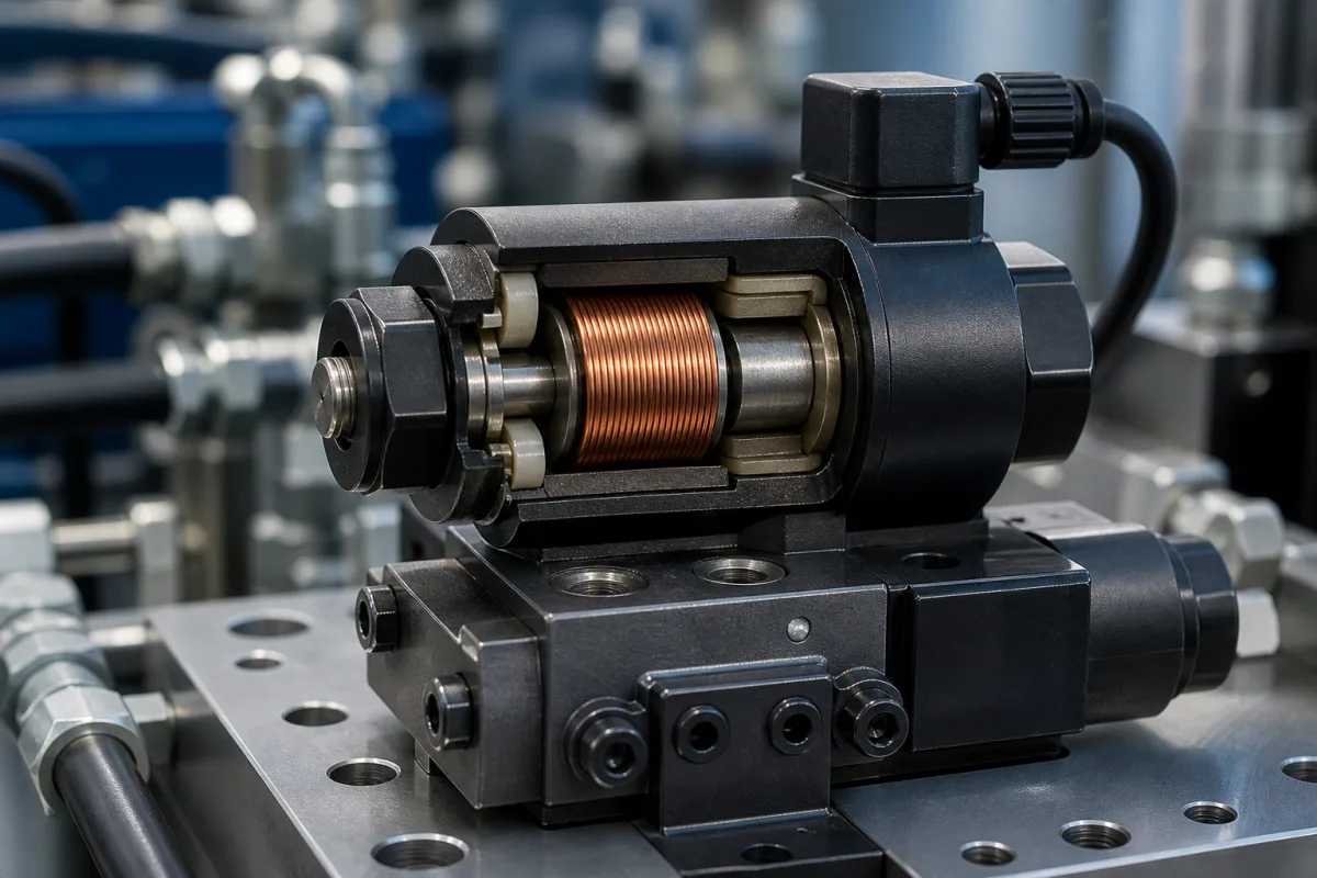
Representative product image. Confirm appearance and specifications with the manufacturer.

Product Specifications

Technical details and manufacturing context for Solenoid Coil

Definition
A solenoid coil is the electromagnetic actuator component within control valves that generates a magnetic field when energized by an electrical current. This magnetic field creates linear motion in a ferromagnetic plunger or armature, which directly opens or closes the valve orifice to control fluid flow. It serves as the primary electromechanical interface between control systems and valve operation. The coil typically consists of copper wire wound around a bobbin, insulated with electrical insulation materials, and enclosed in a protective housing. The ferromagnetic core material is part of the plunger assembly. When selecting a solenoid coil, the user must verify the coil dimensions (including outer diameter, length, and mounting dimensions) against the specific valve model and application requirements. The coil's performance is influenced by the electrical supply (voltage, current, duty cycle) and environmental conditions, but these are not specified in the directory. The coil is a component, not a standalone valve; it must be integrated with a valve body and plunger. For proper operation, the coil must be matched to the valve's electrical and mechanical specifications. Maintenance signals include overheating, intermittent operation, or failure to actuate, which may indicate coil burnout or insulation degradation. Verification questions include: What is the coil's rated voltage and current? What are the exact mounting dimensions? What is the duty cycle? What is the ambient temperature range? Always confirm model-specific values and standards with the legal manufacturer or supplier before procurement or installation.
Working Principle
When electrical current flows through the coiled wire, it generates a magnetic field according to Ampère's law. This magnetic field magnetizes a movable ferromagnetic core (plunger), creating an attractive force that pulls the plunger into the center of the coil. This linear motion is transferred to the valve mechanism to open or close the flow path. De-energizing the coil releases the plunger, typically via a return spring.
Common Materials
Copper wire, Electrical insulation materials, Ferromagnetic core material, Protective housing
Technical Parameters

What to specify in your RFQ

  • Coil dimensions including outer diameter, length, and mounting dimensions in mm

These are the quantities to specify to the manufacturer when sizing or requesting a quote. The manufacturer's own documentation governs the exact figures and applicable standard.

Components / BOM
  • Wire Winding Part
    Conducts electrical current to generate magnetic field
    Material: Copper or aluminum wire
  • Bobbin Part
    Provides structural support and electrical insulation for windings
    Material: Thermoplastic or thermoset polymer
  • Terminal Connections Part
    Electrical interface for power supply connections
    Material: Brass or copper alloy
  • Protective Housing Part
    Provides mechanical protection and environmental sealing
    Material: Plastic, aluminum, or stainless steel

Applied To / Applications

This component is essential for the following industrial systems and equipment:

Industrial Ecosystem & Supply Chain Structure

Complementary Systems
Downstream Applications
Specialized Tooling

Application Fit & Sizing Matrix

Operational Limits
pressure: Up to 6000 psi (414 bar) depending on valve body rating
other spec: Voltage tolerance: ±10% of rated voltage, Duty cycle: Continuous or intermittent (typically ≤90% ON time)
temperature: -20°C to +80°C (standard), up to +120°C (high-temp variants)
Media Compatibility
✓ Hydraulic oil (mineral-based) ✓ Compressed air (dry, filtered) ✓ Water/glycol mixtures
Unsuitable: Corrosive chemicals (acids, strong bases) or abrasive slurries with >5% solids concentration
Sizing Data Required
  • Required force/stroke (N/mm)
  • Supply voltage/current (V DC/AC, mA)
  • Response time/cycle frequency (ms, Hz)

Reliability & Engineering Risk Analysis

Failure Mode & Root Cause
Coil burnout
Cause: Overvoltage, excessive current due to mechanical binding, or prolonged energization beyond duty cycle
Insulation degradation
Cause: Thermal cycling, moisture ingress, or chemical exposure leading to short circuits
Maintenance Indicators
  • Audible humming or buzzing during operation indicating loose laminations or armature sticking
  • Visible discoloration, charring, or swelling of the coil housing suggesting overheating
Engineering Tips
  • Implement voltage regulation and surge protection to maintain electrical parameters within manufacturer specifications
  • Establish preventive maintenance schedules for cleaning, lubrication of moving parts, and insulation resistance testing

Indicative industry ranges for design and RFQ preparation. Confirm the exact figures and applicable standard with the manufacturer before specifying.

Compliance & Manufacturing Standards

Applicable Standards
IEC 60034-1 (Rotating Electrical Machines) EN 60335-1 (Household and Similar Electrical Appliances Safety)

Quoted from the published standard.

Manufacturing Precision
  • Coil Resistance: +/-5% of nominal value
  • Insulation Thickness: +/-0.1mm
Quality Inspection
  • Insulation Resistance Test (Megger Test)
  • Coil Continuity and Resistance Verification

Manufacturers of Solenoid Coil

Manufacturer profiles associated with Solenoid Coil.

Sourcing Solenoid Coil from China?
Tell us your specification and target quantity — we will match it against manufacturer records and come back with the factories that fit.
Request manufacturers We manufacture this

Manufacturer listings support early research and capability understanding. They are not certification, ranking, or transaction guarantees.

Technical documentation
Request current drawings, revision history, and a signed specification sheet.
Manufacturing capability
Verify equipment lists, process limits, capacity, and representative production evidence.
Inspection readiness
Confirm test methods, calibrated equipment, sampling plans, and traceable reports.
Supplier transparency
Check the legal entity, factory address, ownership, certifications, and direct contacts.

CNFX does not score or rank suppliers. Buyers must verify all claims and documents with the legal manufacturer before ordering.

Supply Chain Compatible Machinery & Devices

Heavy-Duty CNC Plasma Cutting Machine

The Heavy-Duty CNC Plasma Cutting Machine is a standalone industrial device designed for cutting conductive metals such as steel, stainless steel, aluminum, and copper alloys.

Explore Specs →
Automated Powder Coating System

Integrated industrial system for applying dry powder coatings to metal substrates.

Explore Specs →
Centrifugal Pump Impeller

The centrifugal pump impeller is a critical rotating component that converts mechanical energy from the motor into kinetic energy in fluid systems.

Explore Specs →
High-Precision CNC Laser Cutting Machine

Computer-controlled industrial machine using focused laser beams to cut sheet metal with micron-level accuracy.

Explore Specs →

Frequently Asked Questions

What is a solenoid coil used for?

A solenoid coil is used in control valves to convert electrical energy into linear mechanical force, which actuates the valve to open or close, thereby controlling fluid flow.

What materials are typically used in a solenoid coil?

Common materials include copper wire for the winding, electrical insulation materials, ferromagnetic core material for the plunger, and a protective housing.

How do I select the right solenoid coil?

You must verify the coil dimensions (outer diameter, length, mounting dimensions) and electrical specifications (voltage, current, duty cycle) against your valve model and application. Always confirm with the manufacturer.

What are signs of a failing solenoid coil?

Signs include overheating, intermittent operation, or failure to actuate. These may indicate coil burnout or insulation degradation. Check electrical supply and mechanical alignment.

Data Basis

Editorial classification, named public sources where available, and source-reviewed manufacturer records.

Preliminary Technical Classification
This page supports structured research, RFQ preparation, and supplier evaluation. It does not replace buyer-led supplier qualification, standards review, or technical approval.
Buyer enquiry

Request manufacturing insight for Solenoid Coil

Ask for use case, specification boundaries, supplier type, and RFQ preparation information for this product.

Where it goes
Straight to the CNFX editorial desk, and to the manufacturer if this product is linked to a claimed profile. Nothing is broadcast to a supplier list.
Your details stay here
We do not sell or rent enquiry data, and we do not add you to a mailing list. Used only to answer this request.
No commission, no middleman
CNFX is a directory. We take no cut of any order and never negotiate on a supplier's behalf.
What we don't claim
A listing is not an endorsement. Qualify every supplier and verify every figure yourself before ordering.

Your business information is used only to process this request.

Thank you! Your message has been sent. We'll respond within 1–3 business days.
Sorry, we couldn't send your message. Please try again, or email us at contact@cnfx.com.

Need to Manufacture Solenoid Coil?

Compare manufacturer profiles with relevant product and process capability.

Previous Product
Z-axis Ram/Spindle
Last Product
Get QuotesChat