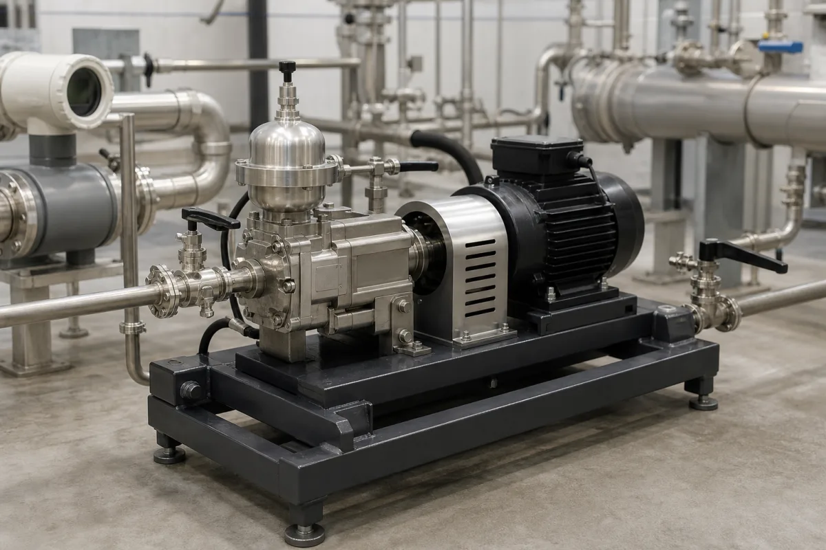
Precision calibration pump for flowmeter test rigs: the flow source that must hold rate within ±2.5 % to ±5 % while meters are checked against a weigh tank or reference meter
The pump that drives water through a flowmeter test rig · flow steadiness the test standard demands, pump types from millilitres to 1,800 L/min, and the heat and ripple a pump adds
In a liquid flowmeter calibration rig the pump is not the measuring instrument: the weigh tank, volumetric tank or reference meter is. The pump's job is to push water through the meter under test at a chosen rate and keep that rate still while the reference device collects its reading. That puts the emphasis on steadiness of flow and supply pressure, on ripple, and on how much heat the pump adds to the water during a long run, rather than on the dose accuracy that sells a chemical metering pump. The pictured unit shows the usual arrangement for a test bench: an electric motor and coupling guard on a steel base, a positive-displacement pump head, and a dome-shaped pulsation dampener on the discharge.
Pumps and pump sets used as the flow source in liquid flowmeter and water-meter calibration rigs, with their speed control, pulsation dampening and the flow-stability, pressure and temperature conditions the test standard places on them. Dosing pumps that inject a measured chemical volume are covered on the Metering pump page; ceramic piston filling pumps on the Precision metering pump for filling and dispensing page; resin gear metering pump and valve sets on the Metering pump/valve set for resin page; hygienic beverage additive dosing pumps, CIP dosing units and packaged dosing skids on their own pages. Complete calibration rigs for electromagnetic flowmeters, with their weighing tanks, diverters, head tanks and reference meters, are covered on the Water flow calibration rig for electromagnetic flowmeters page; this page deals with the pump set alone. Gas flow standards and piston provers are outside this page.
CNFX editorial research · Sources checked October 13, 2026 · 5 sources
Holding the rate still: OIML R 49-2 limits on flow, pressure and temperature during a water-meter test
OIML R 49-2 names variations in pressure, flow rate and temperature in the test rig as the principal factors affecting the measured error of a water meter. [1] Every one of them traces back to the flow source.
The flow-rate value in R 49-2 is the actual volume passed during the test divided by the time, and the reference device must determine that volume with an expanded uncertainty no greater than one-fifth of the meter's maximum permissible error for type evaluation and one-third for initial verification. [1] The pump does not enter that budget directly, but an unsteady rate makes the meter under test read a different flow from the average the tank collects.
Researchers at China's National Institute of Metrology write that the flow stability of a facility “largely depends on the stability of the pressure source” and name the centrifugal pump as the main source of fluctuation in a flow standard facility; they put the frequency range of pulsating flow “generally from a fraction of a hertz to several hundred hertz”, some of it at a natural frequency caused by the pump. [3] Their fluctuation generator was tested on NIM's hot water flow standard facility at 50 m³/h, where a 1 Hz command produced a pipeline pressure wave measured at 1.022 Hz. [3]
Quantity during the test
Limit in OIML R 49-2:2013
What it asks of the pump set
Flow rate, Q1 to Q2 (exclusive)
Relative variation not more than ±2.5 % (starting and stopping excluded) [1]
Steady speed and low ripple at the low end of the meter's range
Flow condition accepted if pressure (flow to free air) or pressure loss (closed circuit) varies by not more than ±5 % below Q2 and ±10 % from Q2 to Q4 [1]
A pressure transmitter downstream of the pump can show compliance
Supply pressure, meters Q3 ≤ 16 m³/h at ≤ 0.1 Q3
Constancy achieved by feeding from a constant head tank; other supplies allowed if their pressure pulsations do not exceed those of a constant head tank [1]
A pump fed directly into the meter must match a head tank's steadiness
Upstream pressure, all other tests
Not more than 10 % variation; pressure measured to 5 % (k = 2) [1]
Speed control or a back-pressure arrangement
Water temperature
Not more than 5 °C change during a test; measured to within 1 °C [1]
Limits pump heat input over the run
Ask how the pump set's flow steadiness was measured (over the test duration, at which flow and with which dampening), and whether the rig can show the ±2.5 % and ±5 % limits through pressure records.
02
Micro annular gear pumps for millilitre benches, banks of 75–112 kW centrifugal pumps for a 1,800 L/min loop
The flow range of the meters to be calibrated decides the pump type more than any other figure.
At NIST the flow is set by valves rather than pump speed: a main valve and a bypass throttle valve near the pumps return part of the water to the reservoir, and fine and coarse valves downstream of the test section set flow and pressure at the meter. [2] An additional flowmeter is used to set the test flows and monitor flow stability while the gravimetric standard collects water. [2]
Editorial calculation: the four NIST pump motors add up to 411 kW (3 × 112 + 75) for a 1,800 L/min ceiling. The mzr-11508X1F's 8 to 1,000 mL/min is a turndown of 125 to 1, while NIST's calibration band of 40 to 1,600 L/min is 40 to 1. [2][4]
Editorial calculation: a pump quoted at 6.3 % peak-to-peak pulsation swings about ±3.15 % around its mean, wider than the ±2.5 % flow variation R 49-2 allows below Q2; one at 1.5 % peak to peak swings about ±0.75 %. R 49-2 applies its limit to the rate during the test, so the figure to request is the variation measured at the meter under test after dampening, not the bare pump figure. [5][1]
Example
Pump and drive
Flow
Other published data
HNP Mikrosysteme mzr-11508X1F, supplied for calibrating and testing flow meters
Micro annular gear pump, 24 V DC brushless servomotor with controller
8 to 1,000 mL/min of demineralised water
1 bar, 1 cP; wetted parts 316 stainless steel, tungsten carbide, graphite-reinforced PTFE, FPM [4]
HNP Mikrosysteme MZR range (distributor figures)
Magnet-drive micro annular gear pumps
1 µL/h to 1 L/min
Pumping accuracy better than 1 %; flow pulsation 1.5 to 6.3 % peak to peak; 0 to 200 bar differential [5]
NIST Water Flow Calibration Facility (WFCF 3700/100)
Four constant velocity centrifugal pumps: three on 112 kW motors, one on 75 kW
Calibrations 40 to 1,600 L/min; usable from 10 to 1,800 L/min
Reservoir about 230 m³; manifold feeding three test lines and a 200 mm bypass [2]
State the smallest and largest flow of the meters to be tested, the liquid and its viscosity, the line sizes, and whether flow will be set by pump speed, by valves with a bypass, or both.
03
Pump heat in a long gravimetric run: 0.2 K per hour at NIST against R 49-2's 5 °C allowance
A closed-loop rig recirculates the same water, so the pump's losses end up as a slow temperature climb in the test liquid.
NIST's facility has no temperature control; pump heating raises the water temperature during the test procedure at about 0.2 K per hour, so only room-temperature calibrations are offered. [2] Its gravimetric standard weighs water collected in a 3,700 kg tank over a timed interval, with an expanded flow uncertainty of 0.033 % when a full tank is weighed (k = 2). [2]
Editorial calculation: at 0.2 K per hour it would take 25 hours to use up the 5 °C temperature change R 49-2 permits within a single test (5 ÷ 0.2). Filling the 3,700 kg tank at NIST's 1,600 L/min upper calibration flow takes about 2.3 minutes, taking 998 kg/m³ as an example value for water density (3,700 ÷ 998 ≈ 3.71 m³; 3,710 L ÷ 1,600 L/min). [2][1]
Where the rig does have a temperature band to hold, for example for heat meters or viscosity-sensitive meters, the pump's heat input becomes part of the chiller or heat-exchanger sizing; NIST notes that calibration curves need compensation for water viscosity, density and the meter's thermal expansion. [2]
Give the test temperature band, the longest run at the highest flow, and the volume of water in the loop, so the supplier can say whether cooling is needed.
04
Data for a calibration rig pump enquiry
Paste it into your enquiry below or into an email to a maker, then replace every bracket.
Meters to be tested: [type; sizes; Q1 to Q4 or min/max flow]
Liquid: [water/demineralised/other; viscosity; temperature band]
Reference method: [weigh tank; volumetric tank; master meter]
Flow setting: [variable speed; valves and bypass]
Flow steadiness required: [±% over test duration; at which flows]
Pressure at meter inlet: [bar; allowed variation]
Pulsation dampening: [dampener; head tank; buffer vessel]
Wetted materials: [stainless; carbide; seals]
Power supply and control interface
Explore company information and manufacturing capabilities, then discuss the scope of your project with a relevant supplier.
Share this page
Compiled and source-reviewed by the CNFX editorial team.
Each manufacturer above links to the page on that company's own website where the product is listed, with the date we checked it. How we source and review
· Page last updated 13 October 2026
Buyer questions
How steady must the flow be when a water meter is tested?
OIML R 49-2:2013 limits the relative flow variation during each test to ±2.5 % from Q1 to Q2 and ±5.0 % from Q2 to Q4, excluding starting and stopping. [1]
What kind of pump drives a large water flow calibration facility?
NIST's water facility uses four constant velocity centrifugal pumps, three on 112 kW motors and one on 75 kW, and sets the flow with valves and a bypass; it calibrates from 40 to 1,600 L/min. [2]
Which pump suits a low-flow flowmeter test bench?
One example is HNP Mikrosysteme's mzr-11508X1F micro annular gear pump, supplied for calibrating and testing flow meters at 8 to 1,000 mL/min of demineralised water with a 24 V DC brushless servomotor. [4]
Does the pump heat the test water?
Yes. NIST reports a rise of about 0.2 K per hour from pump heating in its facility, which has no temperature control; R 49-2 allows no more than 5 °C change during a test. [2][1]
Sources and what still needs a direct check
Sources checked 2026-10-13. Five documents from four publishers: OIML's water-meter test methods R 49-2:2013, NIST's description of its Water Flow Calibration Facility, a FLOMEKO 2022 paper from China's National Institute of Metrology on flow fluctuation in standard facilities, and two pages from Michael Smith Engineers, a UK distributor of HNP Mikrosysteme gear pumps.