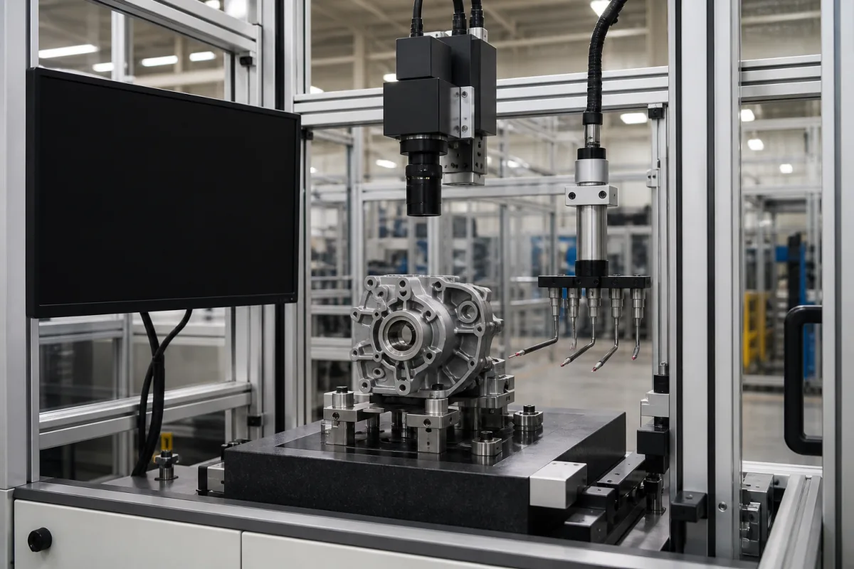
Resonance inspection station for cast, forged and powder-metal parts: whole-part vibration testing against a good-part signature
An end-of-line station that vibrates each casting, forging or sintered part and compares its resonant frequencies with a population of good parts · 0.002 % frequency accuracy, ±1.6 mm part placement, Q above 400–500, and a 1 mm crack that shifts a 4,857 Hz mode by at least 0.72 %
Every solid part rings at a set of natural frequencies fixed by its shape, mass, stiffness and damping. A crack, void, missed heat treatment or wrong density moves those frequencies. A resonance inspection station uses that: it holds each part on a few contact points, drives it through a frequency sweep or taps it, records the resonances and compares them with the spread found in a large population of good parts, giving a go/no-go answer in seconds. It does not say what the defect is or where it is; it says whether the part belongs to the good population.
Resonance-based quality inspection stations for manufactured parts: process compensated resonance testing (PCRT, swept-sine) and resonant acoustic (impact) inspection of castings, forgings, sintered powder-metal, additively manufactured and ceramic parts, with their fixtures, transducers and acceptance criteria. Vibration condition monitoring of running machinery is covered on the Condition monitoring system (machinery) page; end-of-line electrical and NVH tests of assembled motors on the Electric motor final assembly and end-of-line test line page; camera inspection of casting surfaces on the Vision system for cast and machined parts page; leak testing on the Leak testing module page.
CNFX editorial research · Sources checked October 12, 2026 · 4 sources
What ASTM E2534 asks of the station: 0.002 % frequency accuracy, three transducers, ±1.6 mm placement
ASTM E2534 is the practice for process compensated resonance testing with swept-sine input. It compares each part's resonance pattern with reference teaching sets of acceptable parts and parts with targeted defects, and lists the conditions it can separate: cracks, voids, porosity, shrink, inclusions, grain structure, density anomalies, heat-treatment variation, elastic-property differences, residual stress and dimensional variation. [1]
The companion practice for outlier screening, ASTM E3081, states the stiffness limit as a peak Q above 500, and notes that non-rigid materials or very thin-walled parts may not reach it. [2] Editorial note: the two practices give 400 to 500 and above 500; for a new part, measure Q on samples before committing to resonance inspection.
Both practices warn that excessive external vibration or audible noise compromises the measurement, that the nest and cabling must keep drive and receive channels free of mechanical or electrical cross-talk, and that misclassified parts in the teaching set reduce accuracy and sensitivity. [1][2] Among applications in commercial use they list cast cylinder heads and blocks, sintered powder-metal gears and clutch plates, forged steering and transmission parts, gas turbine blades, vanes and disks, and parts made by additive manufacturing or metal injection moulding. [1]
Requirement or limit in ASTM E2534-20 (R25)
Value
Signal generator and response measurement accuracy
Better than 0.002 % over the part's frequency range [1]
Transducers
Three in the set-up the practice describes, one drive and two receive, in contact with the part; non-contact response allowed for wet or oiled parts [1]
Part placement on the transducers
±0.062 in (1.6 mm) in each axis provides acceptable results [1]
Contact with the part
None other than fixture and transducers, since contact damps vibration [1]
Part stiffness
Resonance Q (frequency ÷ width at half maximum) greater than 400 to 500 [1]
Process variation
Mass or dimensional variation over 5 % may make PCRT unusable [1]
Temperature
Part temperature stabilised; not for parts changing temperature rapidly [1]
Give the station builder the part drawing, material and mass range, the defects to be caught, expected production variation, cycle time, and a set of good and known-defective parts for the teaching set.
02
How big a crack it can see: 0.72 % frequency shift from a 1 mm crack in a powder-metal part
The Modal Shop's white paper by Richard Bono and Gail Stultz tested a powder-metal part with a vane. Eighteen production lots of about 5,000 parts each were inspected to build the baseline; acceptance windows were set at about twice the standard deviation of each resonance. [3]
Eighteen labelled parts were measured, cracked by fatigue loading at the base of the vane (two left uncracked as controls), measured again and then sectioned; crack lengths ran from 0.5 to 4.0 mm, examined under a 400x microscope, and the frequency shift grew with crack size, with a linear trend passing through zero. [3] The part maker itself was targeting cracks of 2.0 mm or larger for rejection. [3]
The authors note that narrowing the window from about 2σ to about 1σ would catch smaller cracks at the cost of a scrap rate of about 5 % instead of about 2 %, and that their results cannot be applied across all powder-metal parts because geometry, mass, stiffness and process control differ. [3] Editorial calculation: at 4,857 Hz a 0.72 % shift is about 35 Hz, and the 0.58 % window about 28 Hz wide.
Ask the supplier for a sensitivity study on your own part: known cracks or defects, the frequency shift they cause, and the scrap rate at the proposed window width.
03
Why the good-part population matters more than the hardware
NASA Marshall Space Flight Center's materials and processes laboratory describes PCRT as comparing each part's resonance frequencies with parts of the same type known to be nominal, with sending and receiving transducers in contact and the fixture and transducer set-up kept the same for every specimen. [4]
The Marshall team lists three analysis methods in the commercial software it used: Z-score analysis against a reference population to find gross outliers, vibrational pattern recognition using the Mahalanobis–Taguchi system, and part-to-itself comparison of how a part changes through processing such as heat treatment. Its process sensitivities are practical: consistent geometry is critical, failed additive builds or messy plate removal change shape, and changing build parameters invalidates the previous population. [4]
ASTM E2534 adds the boundary: because PCRT is a whole-body measurement, it calls specific anomaly identification highly unlikely, and it cannot reject parts for visible anomalies that do not affect structural integrity, which may need separate visual inspection. [1] Editorial note: the station in the photograph also carries a camera; a visual check answers a different question from the resonance test, and the two can share one fixture only if the camera adds no contact or vibration during the sweep.
04
What to send for a resonance inspection station
Paste it into your enquiry below or into an email to a maker, then replace every bracket.
Parts: [material; process; mass and dimension range; drawing]
Defects: [cracks, porosity, heat treatment, density; size to reject]
Population: [good parts available; known-defective samples]
Station: [swept-sine or impact; transducer and fixture layout; non-contact needed?]
Throughput: [parts per hour; handling; reject sorting]
Environment: [nearby vibration and noise; part temperature at test]
Acceptance: [sensitivity study; scrap rate at chosen window]
Explore company information and manufacturing capabilities, then discuss the scope of your project with a relevant supplier.
Share this page
Compiled and source-reviewed by the CNFX editorial team.
Each manufacturer above links to the page on that company's own website where the product is listed, with the date we checked it. How we source and review
· Page last updated 13 October 2026
Buyer questions
What does a resonance inspection station measure?
The natural frequencies of the whole part, compared with a teaching set of good and defective parts; ASTM E2534 requires 0.002 % frequency accuracy. [1]
What size crack can resonant inspection detect?
In The Modal Shop's powder-metal study a 1.0 mm crack shifted the 4,857 Hz resonance by at least 0.72 %, outside a 0.58 % window. [3]
Which parts are unsuitable?
ASTM says parts need resonance Q above 400–500 (E3081: above 500), mass or dimensional variation below about 5 %, and stable temperature. [1][2]
Can it tell what the defect is?
No; ASTM E2534 describes PCRT as a whole-body measurement and calls specific anomaly identification highly unlikely. [1]
Sources and what still needs a direct check
Sources checked 2026-10-12. Set-up requirements and limits come from the scope and significance sections of ASTM E2534 and E3081; crack sensitivity from a Modal Shop white paper on a powder-metal part; population-based analysis from a NASA Marshall Space Flight Center poster.