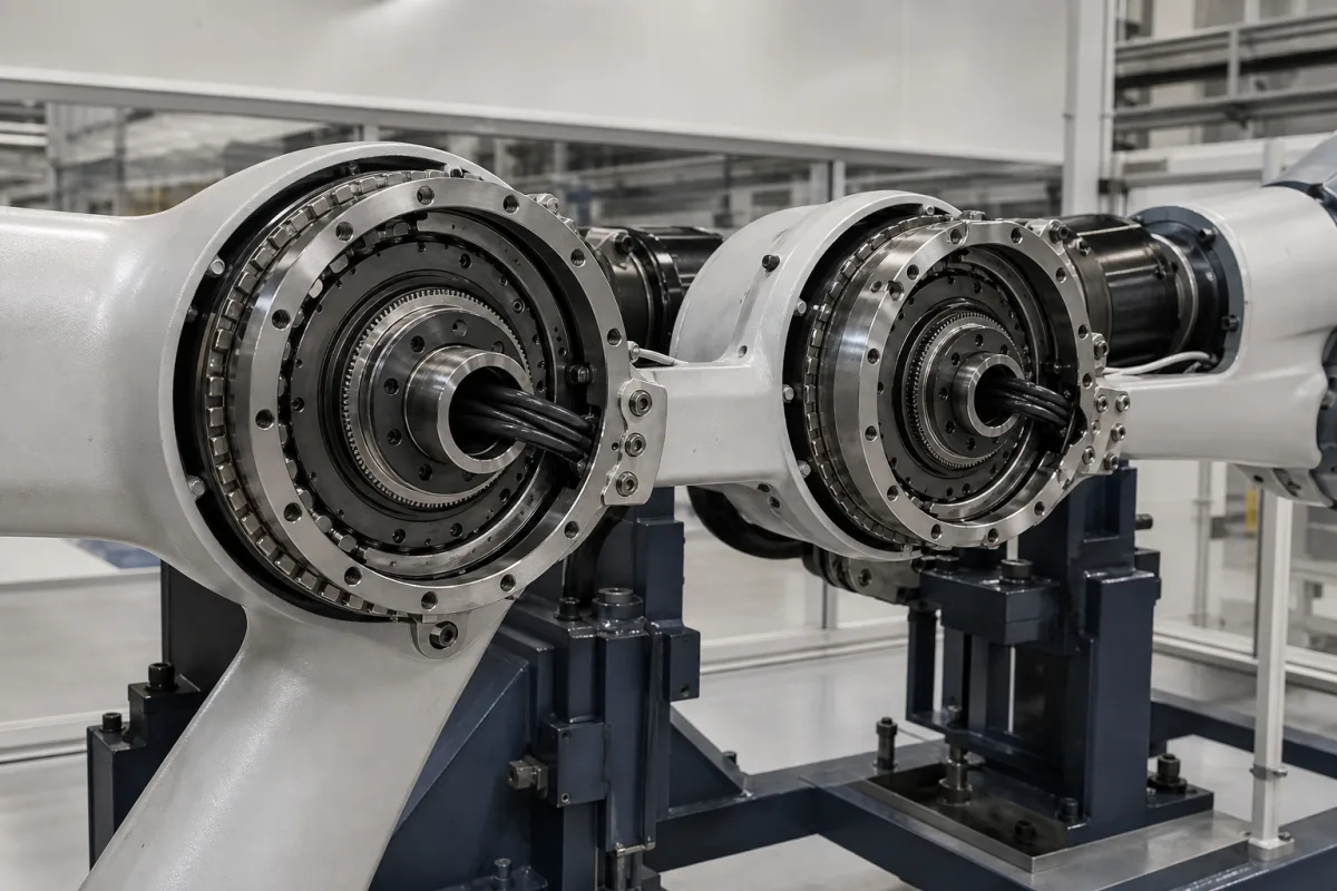
The illustrated arm has two joints opened up: in each, a large thin-section bearing with crossed rollers carries the next link, a gear ring sits inside it, and a bundle of cables passes through the hollow centre. That bearing is what keeps the link from tilting under the payload's moment. THK's selection pages for its cross-roller rings give the calculation, and they add a warning that matters for robots in particular: joints rock back and forth instead of turning continuously.
Covers the main bearing of robot arm rotary joints, the crossed roller bearing: combined radial, axial and moment loads, the dynamic equivalent load with the moment term, nominal and modified life, load factors, static safety, oscillating motion and fretting, and thin-section designs with hollow bores. Robot arms as a whole for press tending, welding cable routing and CMM loading are on 3067, 3190 and 2941; harmonic reducers and their wave-generator bearing on 5163 and 6787; RV joint reducers with their own integral main bearing on Reduction Gears (4463); large slewing rings on Slewing Bearing (7802). RF waveguide rotary joints and hydraulic rotary unions share the name but are outside this page.
CNFX editorial research · Sources checked October 13, 2026 · 3 sources
PIB Sales, a bearing distributor writing on bearings in robotics, describes the crossed roller bearing's place in a robot joint.
The hollow bore in the illustration is the practical gain of a thin-section ring: the cables for the next joints pass through the axis of rotation instead of around it, so they twist rather than bend as the joint turns (editorial reading of the picture).
Because one bearing takes the tilting moment, its moment rating and stiffness, not only its radial rating, bear on how far the link tilts under payload (editorial reading).
Point
What the source states
Construction
Rollers alternately crossed, in line contact with the raceways rather than the point contact of balls, raising rigidity and load capacity (PIB Sales)
Loads
A single crossed roller bearing sustains axial, radial and moment loads at the same time (PIB Sales)
Design effect
It can replace a pair of angular contact bearings in a joint, streamlining the design (PIB Sales)
Thin section
Designed as thin-section rings for wrists and rotating end-effectors; example IKO CRBH7013AUU, 70 mm bore, 100 mm outside diameter, 13 mm wide, about 20.1 kN dynamic and 27.7 kN static load (PIB Sales, distributor figures)
Rating basis
THK's basic dynamic load rating C is the radial load giving 1 million revolutions for 90% of identical rings, load constant in direction and size
The CRBH7013AUU figures are quoted from a distributor's article; check them in IKO's catalogue.
02
Life and static safety with the moment included
THK's selection pages for cross-roller rings set out the life and static checks.
The moment term shows why joint bearings are large in diameter: a 100 N·m tilting moment on a bearing with a roller pitch diameter of about 85 mm adds 2 × 100,000 ÷ 85 ≈ 2,350 N to the radial term (Editorial calculation; 85 mm assumed as the mean of the CRBH7013's 70 and 100 mm diameters). The same moment on a bearing of twice the pitch diameter adds half as much.
Applied to the distributor's CRBH7013AUU figures as an approximation, an equivalent load of 4 kN with fW 1.2 gives (20.1 ÷ (1.2 × 4))^(10/3) ≈ 118 million revolutions, and a static safety of 27.7 ÷ 4 ≈ 6.9, just under THK's recommended 7 (Editorial calculation, using THK's roller-bearing exponent of 10/3 on IKO ratings).
Step
THK
Dynamic equivalent radial load P_C
Combines radial load Fr, axial load Fa and moment M (N·mm), the moment entering as 2M/dp with dp the roller pitch circle diameter, with dynamic radial and axial factors X and Y from THK's table
Nominal life L10
From the basic dynamic load rating C and P_C; total revolutions 90% of identical rings reach without flaking
Modified life L10m
Applies a temperature factor fT and a load factor fW
Load factor fW
1 to 1.2 smooth motion without impact; 1.2 to 1.5 normal motion; 1.5 to 3 excessive vibration or impact
Temperature
Normal service at 80 °C or below; above that consult THK
Static safety fs = C0 / P0
Lower limit 2 without vibration or impact, 5 with; 7 or above recommended considering service life
C0 definition
Static load at which the calculated contact stress at the most loaded contact is 4,000 MPa
THK's formulas apply to its own cross-roller rings; each bearing maker's catalogue method and factors govern its products.
03
Joints rock: oscillating life, small angles and fretting
THK gives a separate service-life formula for oscillatory motion and adds conditions that apply directly to robot joints.
A robot wrist that dithers a few degrees around a working position is the case THK flags: the rollers do not travel far enough to rebuild the oil film, and the raceway wears at fixed points. Programs that park a joint in one position and make small corrections are worth reviewing against the bearing maker's minimum angle (editorial reading).
Condition
THK's guidance
Rotary motion
Service life in hours from L10 and rotation speed; continuous rotation can generate significant heat depending on speed, consult THK
Oscillatory motion
Service life in hours from L10, rocking angle θ and reciprocations per minute
Small oscillation angle
Hinders oil-film formation between raceway and roller and may cause fretting; consult THK
Back-and-forth or low-speed use
May change lubrication requirements; consult THK for the life calculation
Rated life assumption
Optimal mounting and adequate lubrication
THK does not publish a minimum angle on these pages; the value has to come from the bearing maker.
04
What to give a bearing supplier for a robot joint
Paste it into your enquiry below or into an email to a maker, then replace every bracket.
Give the radial, axial and tilting moment loads from payload and arm, including acceleration and emergency stop, the joint's motion profile (rotation or oscillation, angles and cycles), required stiffness, bore needed for cables, temperature, and space envelope. Ask for C, C0 and moment rating, the equivalent-load factors, moment rigidity, preload, sealing, minimum oscillation angle and lubrication interval for oscillating service.
1 company lists this product among what they make. Company figures are quoted from each
company's own website; every card states where the relationship came from.
Explore company information and manufacturing capabilities, then discuss the scope of your project with a relevant supplier.
Share this page
Compiled and source-reviewed by the CNFX editorial team.
Each manufacturer above links to the page on that company's own website where the product is listed, with the date we checked it. How we source and review
· Page last updated 13 October 2026
Buyer questions
Why does a robot joint use a crossed roller bearing?
PIB Sales notes that one crossed roller bearing takes axial, radial and moment loads together and can replace a pair of angular contact bearings in a joint. [3]
How is the moment included in the life calculation?
THK's dynamic equivalent radial load adds the moment as 2M/dp, with dp the roller pitch circle diameter, before applying factors X and Y. [1]
What static safety factor should a joint bearing have?
THK gives a lower limit of 2 without vibration or impact and 5 with, and recommends 7 or above considering service life. [2]
Does oscillating motion change the life?
THK gives a separate oscillating-life formula and warns that too small an oscillation angle hinders oil-film formation and may cause fretting. [1]
Sources and what still needs a direct check
Sources checked 2026-10-13. Two THK selection pages for cross-roller rings and a bearing distributor's article on bearings in robotics.