Editorial Technical Reference

Tension Adjustment System

This page explains how Tension Adjustment System is classified within Machinery and Equipment Manufacturing. Technical values and manufacturer relationships are research references; confirm the current specification and supplier evidence for each order.

Technical Definition & Core Assembly

A mechanical or electromechanical system designed to regulate and maintain optimal tension levels in materials being fed through processing equipment.
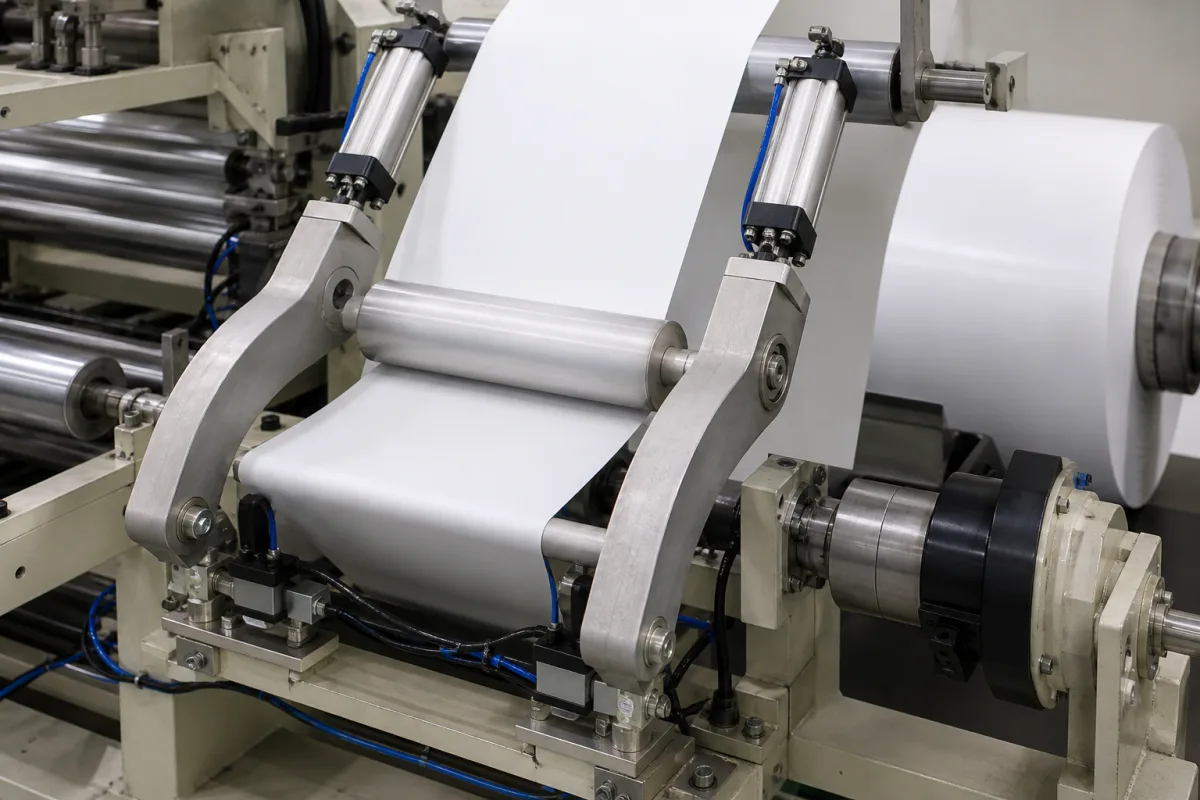
Representative product image. Confirm appearance and specifications with the manufacturer.

Product Specifications

Technical details and manufacturing context for Tension Adjustment System

Definition
The Tension Adjustment System is a component used in the feed mechanisms of processing equipment to control the tension of materials such as fabrics, films, wires, or sheets. Its primary function is to ensure consistent material flow, prevent slack or over-tensioning, reduce material waste, and maintain processing quality. The system dynamically adjusts tension based on real-time feedback from sensors or preset parameters. It typically employs tension sensors such as load cells, dancer arms, or ultrasonic sensors to measure material tension. The measured values are compared to setpoints, and control signals are sent to actuators—such as servo motors, pneumatic cylinders, or magnetic particle brakes—that adjust feed speed, roller pressure, or braking force to maintain desired tension levels. Advanced systems may use closed-loop PID control algorithms for precise regulation. The system is available in configurations using materials such as stainless steel, aluminum alloy, carbon steel, and engineering plastics. Key parameters include a tension range of 50–500 N, tension accuracy of ±1% of setpoint, response time of ≤50 ms for 90% of step change, operating voltage of 24 V DC ±10%, power consumption of ≤120 W at full load, operating temperature of -10 to 50 °C, protection class IP54–IP65 per IEC 60529, material for load cell and rollers of 304 stainless steel per ASTM A240, weight of 15–25 kg depending on configuration, and approximate dimensions of 400×300×200 mm. These values are reference ranges and must be verified for the specific model and application with the legal manufacturer or supplier. The system is intended for integration into machinery and equipment manufacturing applications where precise tension control is critical.
Working Principle
The system measures material tension using sensors such as load cells, dancer arms, or ultrasonic sensors. The measured value is compared to a setpoint, and a controller (often using PID algorithms) generates control signals. These signals drive actuators—servo motors, pneumatic cylinders, or magnetic particle brakes—which adjust feed speed, roller pressure, or braking force to correct any deviation. This closed-loop process continuously maintains the desired tension, ensuring stable material handling.
Common Materials
Stainless steel, Aluminum alloy, Carbon steel, Engineering plastics
Technical Parameters
ParameterTypical rangeNotes & selection driver
Tension Range50–500 NAdjustable within this range
Tension Accuracy±1 %Of setpoint
Response Time≤50 msFor 90% of step change
Operating Voltage24 ±10% V DCFor control electronics
Power Consumption≤120 WMaximum at full load
Operating Temperature-10–50 °CAmbient
Protection ClassIP54–IP65For control cabinetIEC 60529
Material304 SSFor load cell and rollersASTM A240
Weight15–25 kgDepending on configuration
Dimensions (L×W×H)400×300×200 mmApproximate

Ranges are indicative industry figures for RFQ preparation, not a supplier commitment. Confirm every value and standard with the legal manufacturer before ordering.

Components / BOM
  • Tension Sensor
    Measures real-time tension of the material being fed
    Material: Stainless steel with strain gauges
  • Control Unit
    Processes sensor data and sends adjustment commands to actuators
    Material: Aluminum housing with electronic components
  • Actuator
    Executes tension adjustments based on control signals
    Material: Steel with electromagnetic or pneumatic components
  • Guide Rollers Part
    Directs material path and provides contact points for tension application
    Material: Hardened steel or ceramic-coated steel

Applied To / Applications

This component is essential for the following industrial systems and equipment:

Industrial Ecosystem & Supply Chain Structure

Complementary Systems
Downstream Applications
Specialized Tooling

Application Fit & Sizing Matrix

Operational Limits
pressure: 0 to 10 bar
speed range: 0.1 to 100 m/min
temperature: -20°C to 80°C
tension range: 5 to 5000 N
Media Compatibility
✓ Polymer films ✓ Textile fibers ✓ Metal wires
Unsuitable: Abrasive slurries with >20% solids concentration
Sizing Data Required
  • Material width (mm)
  • Maximum line speed (m/min)
  • Required tension range (N)

Reliability & Engineering Risk Analysis

Failure Mode & Root Cause
Bearing fatigue and seizure
Cause: Inadequate lubrication leading to metal-to-metal contact, excessive preload from improper tension settings, or contamination ingress causing abrasive wear
Spring or actuator degradation
Cause: Material fatigue from cyclic loading beyond design limits, corrosion due to environmental exposure, or thermal stress from operating outside temperature specifications
Maintenance Indicators
  • Abnormal high-pitched whining or grinding noises during operation indicating bearing wear or misalignment
  • Visible vibration or irregular movement in tensioning components during system operation
Engineering Tips
  • Implement condition-based monitoring with vibration analysis and thermal imaging to detect early-stage bearing wear and alignment issues
  • Establish precise tension calibration procedures using calibrated torque wrenches or tension gauges, and maintain environmental controls to prevent contamination and corrosion

Indicative industry ranges for design and RFQ preparation. Confirm the exact figures and applicable standard with the manufacturer before specifying.

Compliance & Manufacturing Standards

Applicable Standards
ANSI/ASME B46.1-2019 - Surface Texture

Quoted from the published standard.

Manufacturing Precision
  • Bore diameter: ±0.01 mm
  • Parallelism of mounting surfaces: 0.05 mm
Quality Inspection
  • Torque verification test
  • Hardness testing (Rockwell C scale)

Manufacturers of Tension Adjustment System

Manufacturer profiles associated with Tension Adjustment System.

Sourcing Tension Adjustment System from China?
Tell us your specification and target quantity — we will match it against manufacturer records and come back with the factories that fit.
Request manufacturers We manufacture this

Manufacturer listings support early research and capability understanding. They are not certification, ranking, or transaction guarantees.

Technical documentation
Request current drawings, revision history, and a signed specification sheet.
Manufacturing capability
Verify equipment lists, process limits, capacity, and representative production evidence.
Inspection readiness
Confirm test methods, calibrated equipment, sampling plans, and traceable reports.
Supplier transparency
Check the legal entity, factory address, ownership, certifications, and direct contacts.

CNFX does not score or rank suppliers. Buyers must verify all claims and documents with the legal manufacturer before ordering.

Supply Chain Compatible Machinery & Devices

Automated Powder Coating System

Integrated industrial system for applying dry powder coatings to metal substrates.

Explore Specs →
Centrifugal Pump Impeller

The centrifugal pump impeller is a critical rotating component that converts mechanical energy from the motor into kinetic energy in fluid systems.

Explore Specs →
High-Precision CNC Laser Cutting Machine

Computer-controlled industrial machine using focused laser beams to cut sheet metal with micron-level accuracy.

Explore Specs →
Industrial-Grade Hydraulic Cylinder Piston Rod

This industrial-grade piston rod is a precision-ground cylindrical component designed for use in hydraulic cylinders.

Explore Specs →

Frequently Asked Questions

What is the typical tension range of this system?

The tension range is adjustable within 50–500 N, as listed in the reference parameters. However, the exact range for a specific model must be confirmed with the manufacturer or supplier.

How does the system maintain tension accuracy?

The system uses sensors to measure tension and compares it to a setpoint. Control signals are sent to actuators to adjust feed speed, roller pressure, or braking force. The accuracy is ±1% of setpoint, but this should be verified for the actual configuration.

What are the electrical requirements?

The control electronics require a 24 V DC supply with ±10% tolerance. Power consumption is up to 120 W at full load. Always check the specific model's documentation for exact requirements.

What environmental conditions can it operate in?

The operating temperature range is -10 to 50 °C ambient. The control cabinet has a protection class of IP54–IP65 per IEC 60529. Confirm suitability for your environment with the supplier.

Data Basis

Editorial classification, named public sources where available, and source-reviewed manufacturer records.

Preliminary Technical Classification
This page supports structured research, RFQ preparation, and supplier evaluation. It does not replace buyer-led supplier qualification, standards review, or technical approval.
Buyer enquiry

Request manufacturing insight for Tension Adjustment System

Ask for use case, specification boundaries, supplier type, and RFQ preparation information for this product.

Where it goes
Straight to the CNFX editorial desk, and to the manufacturer if this product is linked to a claimed profile. Nothing is broadcast to a supplier list.
Your details stay here
We do not sell or rent enquiry data, and we do not add you to a mailing list. Used only to answer this request.
No commission, no middleman
CNFX is a directory. We take no cut of any order and never negotiate on a supplier's behalf.
What we don't claim
A listing is not an endorsement. Qualify every supplier and verify every figure yourself before ordering.

Your business information is used only to process this request.

Thank you! Your message has been sent. We'll respond within 1–3 business days.
Sorry, we couldn't send your message. Please try again, or email us at contact@cnfx.com.

Need to Manufacture Tension Adjustment System?

Compare manufacturer profiles with relevant product and process capability.

Previous Product
Z-axis Ram/Spindle
Last Product
Get QuotesChat