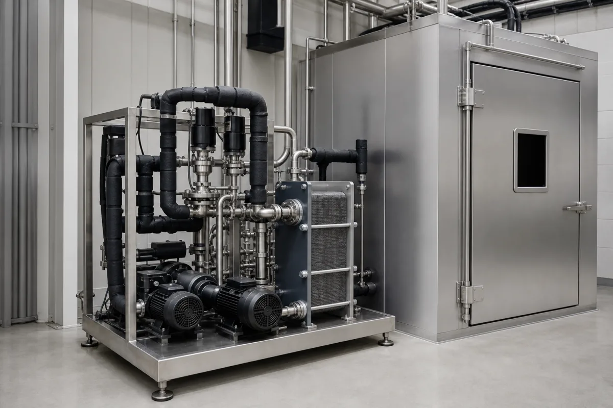
Proving what a calibration chamber's temperature control delivers
The illustrated installation pairs a walk-in chamber with a skid of pumps, insulated pipework and a plate heat exchanger that supplies its heating and cooling. Whatever hardware a chamber's thermal control uses, its result is a gas temperature that varies from place to place and from minute to minute, and a calibration has to put numbers on both. Germany's DKD-R 5-7 guideline, published by PTB in a 2025 edition, and the EURAMET calibration guide on climatic chambers set out how, and an instrument maker shows one sensor layout that meets them.
Covers the thermal control of temperature and climatic chambers used to calibrate or condition sensors and instruments, and how its performance is calibrated: useful volume and measuring locations, spatial inhomogeneity, temporal instability, radiation and loading influence, calibration points and uncertainty. Pressure-sensor calibration systems inside temperature chambers are on 696; temperature control units for reactor jackets on 923; walk-in drying ovens on 2794; hygienic temperature measuring points on 3121. Thermal forcing systems for semiconductor device testing share the name and are outside this page.
CNFX editorial research · Sources checked October 13, 2026 · 3 sources
DKD-R 5-7 applies to chambers whose useful volume, spanned by the measuring locations, has a ratio of largest to smallest extent below 5. For calibration of a whole useful volume (its methods A and B), it fixes the number and position of the measuring locations.
The result holds only for the volume spanned by the measuring points: interpolation inside it is allowed, extrapolation beyond it is not, and the chamber dimensions and sensor positions go into the certificate as a sketch. Calibrating a single measuring location (method C) is also allowed, but then the calibration is not valid for the whole chamber.
Ahlborn's implementation for an on-site calibration uses 8 temperature sensors at the corner points and a digital Pt100 psychrometer at the centre, with relative humidity computed for all 9 points in the data logger.
Useful volume
Measuring locations (DKD-R 5-7)
Up to 2,000 L
Per DIN EN 60068-3-5: the 8 corners and the centre of a cuboid spanning the useful volume (9 locations)
Above 2,000 L
A cubic lattice covering the useful volume, at most 1 m between measuring points
Interior volume up to 1,000 L
Wall distance L/10, at least 50 mm
Over 1,000 to 2,000 L
Wall distance L/10, at least 100 mm
Over 2,000 L
Wall distance L/10, at least 150 mm
For a 1 m cube the L/10 rule puts the sensors 100 mm from the walls (Editorial calculation).
02
Equalisation, temporal instability and spatial inhomogeneity
DKD-R 5-7 does not let measurement start when the chamber reaches setpoint; it starts once the temperatures at all measuring points have shown no systematic change for at least 30 minutes.
Applied to a chamber whose worst corner reads 0.30 K away from the centre, the inhomogeneity contribution alone is a standard uncertainty of 0.17 K before any other term is added (Editorial calculation, 0.30 / √3).
DKD-R 5-7 names the factors that set the waiting time (calibration temperature, interior volume, step between calibration points, ambient conditions, air velocity) and states that equalisation is significantly impaired without gas or air circulation, so the longer times must be taken into account.
Quantity
How DKD-R 5-7 determines it
Uncertainty treatment
Temporal instability
At least 30 values recorded over 30 minutes at the reference location, for each calibration temperature
Maximum deviation from the 30-minute mean, as the half-width of a rectangular distribution: u = max / √3
Spatial inhomogeneity
Maximum deviation of any corner or wall location from the reference location
Half-width of a rectangular distribution: u = max / √3
Calibration points
At least three temperatures across the range; two (start and end) if the range spans no more than 20 K
Single-point calibration limits the result to that operating point
03
Gas temperature versus what a body in the chamber reaches
When the chamber runs away from ambient temperature its walls sit at a different temperature from the gas, and DKD-R 5-7 points out that bodies in the useful volume, thermometers included, then do not reach the gas temperature because they exchange heat by radiation.
EURAMET's guide makes the practical point for users: calibrating the chamber's own indication is "by far not the best method" for documenting the conditions during operation, and laboratories should tell customers so before signing the contract; it points to at least one temperature or humidity sensor in close proximity to the load as the alternative.
DKD-R 5-7 allows a customer-specific alternative: measure gas temperature with a low-emissivity or shielded thermometer and body temperature inside a test body representing the customer's load, with the result restricted to those conditions.
Point
Source
The radiation influence grows with the gas-to-wall temperature difference and more than proportionally with absolute temperature
DKD-R 5-7
Procedure S1: two thermometers at the reference location, one with emissivity above 0.6 and one below 0.15; extrapolate to emissivity 0 for gas temperature
DKD-R 5-7
The high-emissivity sensor: cylindrical, at least 20 mm long and at least 4 mm in diameter
DKD-R 5-7
In S1, 20% of the difference between the two thermometers is taken as the half-width of the radiation contribution
DKD-R 5-7
Loading influence: compared between loaded and empty useful volume, on customer request or as part of loaded-chamber methods
DKD-R 5-7
Ahlborn measures the radiation influence with a double sensor of two different surface emissivities, alongside the 8 corner sensors
Ahlborn
04
What to specify for a calibration chamber's thermal control
Paste it into your enquiry below or into an email to a maker, then replace every bracket.
Give the useful volume and its dimensions, temperature (and humidity) range, the calibration points you need, the load you will place in it and its heat dissipation, and the uncertainty you need for the gas temperature or for a test body. Ask the supplier for spatial inhomogeneity and temporal instability measured to DKD-R 5-7 at your calibration points, equalisation time, radiation influence at the extremes of the range, loaded-versus-empty results, and the calibration certificate format.
Explore company information and manufacturing capabilities, then discuss the scope of your project with a relevant supplier.
Share this page
Compiled and source-reviewed by the CNFX editorial team.
Each manufacturer above links to the page on that company's own website where the product is listed, with the date we checked it. How we source and review
· Page last updated 13 October 2026
Buyer questions
How many sensors are needed to calibrate a climatic chamber?
DKD-R 5-7 requires 9 measuring locations (8 corners and the centre) up to 2,000 L of useful volume, and a cubic grid with at most 1 m spacing above that. [1]
How is temperature stability of a chamber measured?
After at least 30 minutes without systematic change, DKD-R 5-7 records at least 30 values over 30 minutes and takes the maximum deviation from the mean as the instability. [1]
Why does a thermometer in a chamber not read the gas temperature?
Because walls at a different temperature exchange radiation with it; DKD-R 5-7 measures the effect with two thermometers of high and low emissivity, as in Ahlborn's double-sensor setup. [1][3]
Is calibrating the chamber display enough to document test conditions?
EURAMET's guide cg-20 calls calibration of the chamber indication by far not the best method for documenting conditions during operation, and points to a sensor close to the load. [2]
Sources and what still needs a direct check
Sources checked 2026-10-13. The DKD-R 5-7 guideline on calibrating climatic chambers (PTB, edition 01/2025), the EURAMET calibration guide cg-20 (2010), and an instrument maker's description of a DKD-R 5-7 sensor setup.