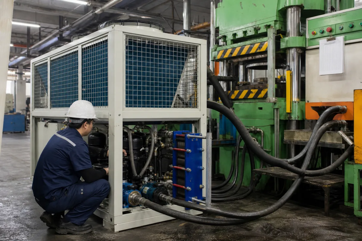
Mould cooling unit for plastic and rubber moulding machines
Machine-side mould cooling · Chiller capacity and leaving water temperature, booster flow per zone, cooling share of the moulding cycle
A mould cooling unit, as used on this page, is the machine-side package that removes heat from a plastic or rubber mould: a refrigeration chiller with its own pump and reservoir, sometimes combined with a temperature controller that heats or boosts flow per mould zone, piped to the mould or press platens by hoses. Ask three things first: how much heat the mould must reject at what water temperature, what flow each mould zone needs, and how the unit's capacity was rated.
Portable and machine-side chillers and combined chiller–temperature control units serving injection, compression and rubber moulding tools and press platens. Automatic die spray units that apply lubricant and blow-off air to die casting dies are covered on the Automated mold spraying and cooling system page; general-purpose process chillers are covered on the Process chiller page. Brewery and distillery glycol cooling units, central plant chillers and cooling towers are outside this page.
CNFX editorial research · Sources checked October 12, 2026 · 3 sources
Size the chiller from the heat and the leaving water temperature
Advantage Engineering's MG-2A portable air-cooled water chiller is a 2-ton, 7.0 kW unit with one 2 hp scroll compressor, refrigerant listed as R-513A in its specification table (its features list names R-410A), a 2,000 CFM condenser fan rated at 95°F ambient, a ¾ hp stainless centrifugal pump delivering 4.8 GPM at 32 psi, a 7.5-gallon reservoir and ¾-inch process connections. [1]
Advantage rates tons at 12,000 BTU/h per ton at 50°F leaving water temperature and 115°F condensing, with capacities ±5% per the compressor maker; it says operating below 50°F reduces capacity, the minimum recommended temperature without glycol is 48°F, the minimum recommended ambient is 60°F and higher ambients reduce capacity. Full-load current is 23 A at 230/3/60 or 12 A at 460/3/60, and the unit measures 32.5 × 37 × 24 in with a shipping weight of 415 lb. [1]
Editorial calculation: 4.8 GPM × 3.785 L/gal ≈ 18.2 L/min, about 0.30 kg/s of water; carrying 7.0 kW at that flow raises the water temperature by 7,000 ÷ (0.30 × 4,186) ≈ 5.5 K across the mould, assuming plain water and the full rated load. [1] Editorial note: compare offers at the same leaving water temperature and ambient, because the rated tons change with both.
Give the supplier the moulding machine and mould, material and shot weight, cycle time, the heat to be removed or the parts per hour, the water temperature wanted at the mould, the number of mould zones and their flow, the ambient where the unit will stand, whether water or glycol is used, supply voltage and the hose connection sizes.
02
Set flow and temperature per mould zone
A 2025 review of injection moulding optimisation in Polymers states that cooling accounts for 50–80% of the cycle time, and that conformal cooling channels following the cavity contour give more uniform cooling, shorter cycles and better part quality; it lists coolant temperature among the variables to optimise for consistent thermal management. [3]
Frigel's Microgel RCD/RCM, now listed as discontinued and replaced by its Microgel RS, is a compact mould cooling unit that combines a water-cooled chiller with one or two high-flow booster-pump temperature controllers, heating elements and a free-cooling valve, synchronised with the moulding machine. Frigel lists over 50 models with one or two temperature zones, a range of −5 to 90 °C ±0.2 °C, chiller capacity of 5 to 200 kW, heating of 6 to 96 kW and booster pumps of 1 to 50 m³/h per zone, and claims cycle time reduction of up to 25% with productivity up to 33% higher. [2]
Editorial calculation: a 25% shorter cycle allows 1 ÷ 0.75 ≈ 1.33 times the cycles per hour, matching Frigel's 33% figure. [2] Editorial note: Frigel's figures are its own claims; ask for flow and temperature readings at mould inlet and outlet for each zone on a trial mould.
03
Compare mould cooling unit types
Type
What it does
Check
Portable air-cooled chiller
Chiller, pump and reservoir in one cabinet; rejects heat to room air. [1]
Rated tons at your water temperature and ambient.
Chiller with booster temperature controllers
Adds per-zone pumps, heaters and free cooling. [2]
Hold set temperature; free-cooling valve on the RCD. [2]
Accuracy; inlet/outlet readings.
05
Capacity at leaving water temperature, flow per zone and control accuracy for a mould chiller
The MG-2A page names two refrigerants, R-513A in its specification table and R-410A in its feature list, so confirm the refrigerant on the unit quoted. [1]
Field
What it means and published values
Ask the supplier for
Cooling Capacity (kW)
7.0 kW (2 tons) for the MG-2A; 5–200 kW across Microgel RCD. [1][2]
Capacity at your water temperature and ambient.
Cooling Water Flow Rate (L/min)
4.8 GPM (≈18.2 L/min, editorial conversion) for the MG-2A; 1–50 m³/h per booster zone on the RCD. [1][2]
Flow per zone at mould pressure drop.
Cooling Water Inlet Temperature (°C)
Ratings at 50°F leaving water; 48°F minimum without glycol (MG-2A). [1]
Explore company information and manufacturing capabilities, then discuss the scope of your project with a relevant supplier.
Share this page
Compiled and source-reviewed by the CNFX editorial team.
Each manufacturer above links to the page on that company's own website where the product is listed, with the date we checked it. How we source and review
· Page last updated 13 October 2026
Buyer questions
How much of the moulding cycle is cooling?
A 2025 Polymers review states that cooling accounts for 50–80% of injection moulding cycle time. [3]
What does a 2-ton portable mould chiller deliver?
Advantage's MG-2A delivers 7.0 kW at 50°F leaving water and 115°F condensing, with a 4.8 GPM pump at 32 psi. [1]
Why add booster temperature controllers?
Frigel's Microgel RCD adds per-zone booster pumps of 1–50 m³/h and heaters, holding −5 to 90 °C ±0.2 °C. [2]
Sources and what still needs a direct check
Sources checked 2026-10-12. Advantage Engineering and Frigel are makers of process chillers and mould temperature control units describing their own products; the Polymers review is a peer-reviewed open-access article.