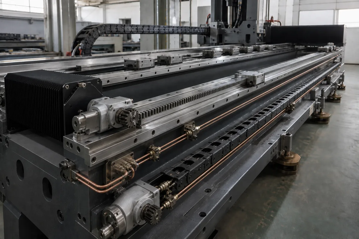
X-axis rails and drive for long gantry beds: two pinions on one rack, electrically preloaded at 10–30 % of motor torque to remove backlash over the whole travel
The long X axis of a gantry machine, driven by two motor–gearbox–pinion units on one rack and preloaded against each other · why racks for long travel, how much preload, and what it buys in path error
On laser and plasma cutting machines, gantry milling machines and large routers the X axis runs the length of the bed. Kitamura's patent notes that ball-screw feed is limited in speed, and ISW that a rack drive's stiffness does not depend on travel, which is why long axes are driven through racks. The price is backlash between pinion and rack and inside the gearbox. The answer used on machine tools is to drive the axis with two motor–gearbox–pinion units engaging the same rack, and to have the control hold one pinion against the opposite tooth flank to the other, so that one of the two always carries load without play. How much preload is applied is a trade-off between stiffness and path accuracy on one side and energy and wear on the other. The picture shows such an axis: a long machine bed with profile rails and carriages, a helical rack along its edge, two servo gearboxes with pinions at the end, copper lubrication lines and cable chains running the length of the bed.
The longitudinal (X) axis drive of long-bed gantry machines built from profile rails, a rack and two motor–gearbox–pinion units preloaded against each other electrically (master–slave) or mechanically: preload level, control and position feedback, rack orientation and tooth form. Butt-jointed long profile rails and their lubrication are covered on the Linear guideways for long axes page; racks and pinions as components on the Rack and pinion page; multi-axis XY tables and XYZ stages on the XYZ positioning stage page; heavy handling gantries with synchronised dual drives on the Gantry system for heavy loads page; the beam and rail track of thermal cutting machines on the Cutting gantry page; motors for CNC router axes on the Axis drive motors for CNC router gantries page.
CNFX editorial research · Sources checked October 13, 2026 · 4 sources
Two drives on one rack: why long axes use racks, and how a second pinion takes out the backlash
The Institute for Control Engineering of Machine Tools (ISW) at the University of Stuttgart notes that rack-and-pinion drives suit machine tools because their stiffness is independent of the travel range, so long movements can be realised, and that their accuracy is limited by transmission errors and by backlash in the gearbox and between rack and pinion. [1]
Its remedy is to electrically preload two redundant drives. Long travel makes direct linear scales a major cost of the axis, so the ISW Master-Switch project closes the position loop on the motor encoders instead, switching to the encoder of whichever motor is transmitting force; with preload, backlash never opens in both drives at the same time. [1]
Kitamura Machinery's patent applies the same principle to all three axes of an NC machine tool: each feed mechanism uses a rack and pinion with two motors, which doubles the driving force, and backlash is removed by preloading. It specifies helical or double-helical rack-pinions for smoother feed, and horizontal racks mounted with the teeth facing down or sideways so that foreign matter cannot settle on the tooth faces. [3]
A trade description of WITTENSTEIN's master–slave rack set gives the sequence over a move: at standstill the electronic preload is at its maximum with the two powered pinions pushing on opposite tooth flanks; during acceleration the master drives while the slave eases off; at steady speed both drive in the same direction without backlash; during deceleration the slave returns to the opposing flank and helps slow the load. [4]
Ask whether preload is electrical (two motors under master–slave control) or mechanical, which encoder closes the position loop, and whether the two drives can add their torque for heavy acceleration.
02
How much preload: 10–30 % of nominal torque at commissioning, and the path error at minimum and maximum
Steinle, Leipe, Lechler and Verl (ISW) measured on a two-drive test system what the preload level does to path accuracy and energy, and proposed adapting it during operation.
The authors state that preload torque is set to a constant value at commissioning, specified as a percentage of the motors' nominal torque and set empirically at 10 to 30 % (typ.), and left there during operation; the constant preload causes significant energy consumption and wear, while higher preload gives a stiffer, more dynamic drive. [2] In point-to-point moves at 1 to 4 m/s², mean absolute path error was 47 to 56 µm at minimum preload, 29 to 34 µm at maximum preload and 30 to 35 µm with their adaptive preload, which held 1.8 to 2.7 Nm and averaged 77 % less preload torque than the maximum. [2]
Editorial calculation: on that rig, nominal motor torque through the 16:1 gearbox is about 160 N·m at the pinion, or about 3.77 kN at the 42.44 mm pitch radius, ignoring gearbox losses; an example preload of 20 % (2 Nm at the motor, inside the 10–30 % band) would press the pinions against opposite flanks with about 0.75 kN (2 × 16 ÷ 0.04244). [2]
Ratio 16; module 4 mm; helix angle 19.5283°; pinion pitch diameter 84.882 mm [2]
Moved mass
Table 400 kg on Schneeberger guide rails with integrated linear measuring system [2]
Preload range tested
Minimum 0.52 Nm (static friction); maximum equal to nominal torque [2]
Ask for the commissioned preload as a percentage of nominal torque, whether it adapts with acceleration, and the path error measured at your acceleration.
03
Data for an X-axis rack drive enquiry
Paste it into your enquiry below or into an email to a maker, then replace every bracket.
Machine: [laser/plasma cutter; gantry mill; router; other]
Travel: [mm]
Moved mass and acceleration: [kg; m/s²]
Speed: [m/min]
Rack: [module; helical/straight; tooth orientation]
Drives: [two per rack; per side; motor and gearbox]
Preload: [electrical master–slave; mechanical; % of nominal torque; adaptive]
Position feedback: [motor encoders; linear scale]
Path accuracy target: [µm]
Explore company information and manufacturing capabilities, then discuss the scope of your project with a relevant supplier.
Share this page
Compiled and source-reviewed by the CNFX editorial team.
Each manufacturer above links to the page on that company's own website where the product is listed, with the date we checked it. How we source and review
· Page last updated 13 October 2026
Buyer questions
Why use racks instead of ball screws on long axes?
The University of Stuttgart's ISW notes that rack-and-pinion stiffness is independent of the travel range, so long movements can be realised. [1]
How is backlash removed from a rack-and-pinion X axis?
Two motor–gearbox–pinion units drive the same rack and one is preloaded against the other; Kitamura's patent uses two motors per axis, and ISW describes electrically preloading two redundant drives. [3][1]
How much preload torque is used?
Steinle et al. give 10–30 % of the motors' nominal torque (typ.), set at commissioning; their adaptive scheme ran at 1.8–2.7 Nm on 10 Nm motors. [2]
Does preload improve accuracy?
In their tests, mean path error was 47–56 µm at minimum preload and 29–34 µm at maximum preload for accelerations of 1 to 4 m/s². [2]
Sources and what still needs a direct check
Sources checked 2026-10-13. Four documents from three publishers: the University of Stuttgart ISW Master-Switch project page and the ISW paper by Steinle et al. in Production Engineering (2025) on preload adaptation, Kitamura Machinery's European patent application EP 1 270 143 A1, and an American Machinist report on WITTENSTEIN's master–slave rack set.