Editorial Technical Reference

Gantry System

This page explains how Gantry System is classified within Machinery and Equipment Manufacturing. Technical values and manufacturer relationships are research references; confirm the current specification and supplier evidence for each order.

Technical Definition & Core Assembly

A structural framework with a bridge-like configuration that supports and guides moving equipment along multiple axes within an industrial system.

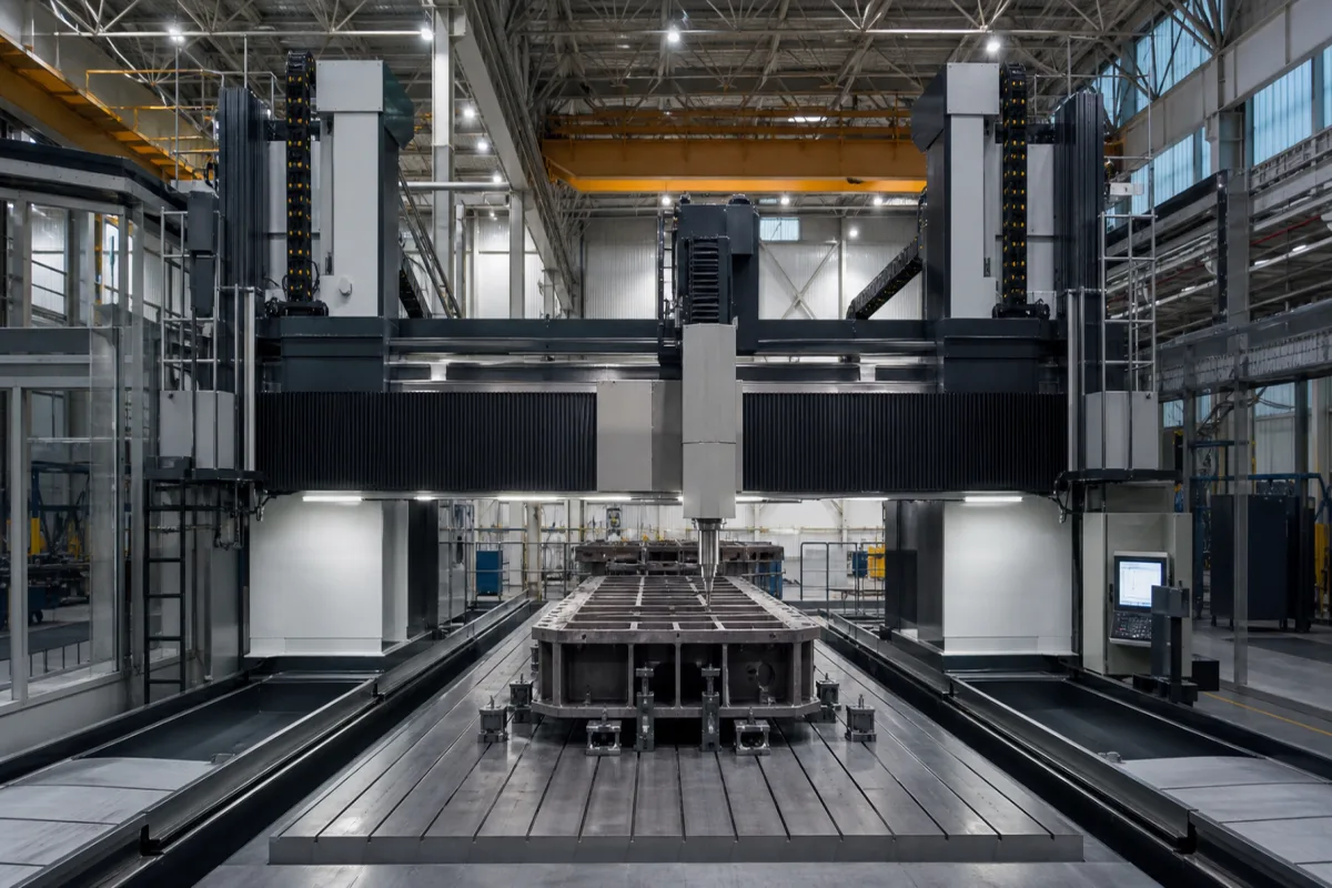
Representative product image. Confirm appearance and specifications with the manufacturer.

Product Specifications

Technical details and manufacturing context for Gantry System

Definition
A Gantry System is a critical structural component within an Industrial System, characterized by a rigid overhead framework (the gantry) that spans a work area. It provides a stable, multi-axis platform for mounting and precisely moving tools, sensors, or end-effectors (such as robotic arms, welding heads, or CNC spindles) to perform operations over a large, fixed workspace. Its primary role is to enable high-precision positioning and manipulation across the X, Y, and often Z axes, facilitating automated manufacturing, material handling, assembly, or inspection processes. The system typically consists of two parallel support legs connected by a horizontal beam, forming a bridge-like structure. Linear guides or rails are mounted on the beam and legs, allowing carriages to move along each axis. The gantry is designed to handle significant loads while maintaining rigidity and accuracy. Common materials include structural steel (e.g., A36) and aluminum alloy (e.g., 6061-T6). The system is available in various configurations with travel lengths ranging from 1000 to 6000 mm on the X-axis, 500 to 3000 mm on the Y-axis, and 200 to 1000 mm on the Z-axis. Load capacity varies from 500 to 5000 kg per axis, and positioning accuracy is typically ±0.05 to ±0.1 mm with repeatability of ±0.02 to ±0.05 mm, per ISO 230-2. Maximum speed ranges from 0.5 to 2.0 m/s, and drive power from 1.5 to 15 kW. The system operates on a three-phase supply of 380 V AC (±10%) per IEC 60038, within an operating temperature of -10 to 50°C, and offers ingress protection ratings of IP54 to IP65 per IEC 60529. Frame materials may include steel grades Q235 to Q345 per GB/T 700, with stainless steel optional. Machine weight ranges from 1500 to 8000 kg, and footprint dimensions from 2000×1500 to 8000×4000 mm. These values are reference ranges; verify model-specific specifications with the manufacturer.
Working Principle
The Gantry System operates by providing a rigid, elevated track or rail structure. A carriage or crossbeam, mounted on this structure, moves along the primary (typically X) axis. A tooling platform or secondary carriage on this crossbeam moves along the perpendicular (Y) axis. This creates a planar coordinate system. For 3D operation, a Z-axis actuator is mounted on the Y-axis carriage, allowing vertical movement. The system is driven by servo motors or linear actuators coupled with precision ball screws, rack-and-pinion drives, or linear motors. Motion controllers coordinate the movement along all axes based on programmed paths, enabling the attached tool to reach any point within its volumetric envelope with high accuracy and repeatability.
Common Materials
Structural Steel (e.g., A36), Aluminum Alloy (e.g., 6061-T6)
Technical Parameters
ParameterTypical rangeNotes & selection driver
Load Capacity500–5000 kgMaximum load per axis; higher loads require larger frame sections.
Travel Length (X-axis)1000–6000 mmCustom lengths available upon request.
Travel Length (Y-axis)500–3000 mmBridge width; affects footprint.
Travel Length (Z-axis)200–1000 mmVertical stroke for tooling or workpiece.
Positioning Accuracy±0.05–±0.1 mmDepends on drive system and feedback resolution.ISO 230-2
Repeatability±0.02–±0.05 mmCritical for automated processes.ISO 230-2
Maximum Speed0.5–2.0 m/sLimited by motor power and inertia.
Drive Power1.5–15 kWTotal for all axes; varies with load and speed.
Supply Voltage380 ±10% V ACThree-phase; other voltages on request.IEC 60038
Operating Temperature-10–50 °CBelow -10°C may require special lubrication.
Ingress ProtectionIP54–IP65Higher IP for dusty or wet environments.IEC 60529
Frame MaterialQ235–Q345Steel grades; stainless steel optional.GB/T 700
Machine Weight1500–8000 kgDepends on size and configuration.
Footprint (L×W)2000×1500–8000×4000 mmApproximate; includes control cabinet.

Ranges are indicative industry figures for RFQ preparation, not a supplier commitment. Confirm every value and standard with the legal manufacturer before ordering.

Components / BOM
  • Gantry Bridge/Beam
    The primary horizontal structural member that spans the work area, providing the track for the Y-axis carriage.
    Material: Structural steel or aluminum alloy profile.
  • X-Axis Rails & Drive
    Provides the longitudinal track and propulsion system for the entire gantry bridge to move along the X-axis. Typically includes linear guide rails and a ball screw or linear motor drive.
    Material: Steel rails, ball screw (steel), or linear motor components.
  • Y-Axis Carriage & Drive
    The moving platform that travels along the gantry bridge (Y-axis). It carries the Z-axis assembly or tool head and is driven by its own linear drive system.
    Material: Aluminum or steel plate with integrated bearing blocks.
  • Z-Axis Actuator Optional
    Provides vertical motion for the tool head or end-effector. Can be a ball screw actuator, linear motor, or pneumatic cylinder.
    Material: Aluminum housing, steel ball screw or rod.
  • Control System & Motors
    The electronic control unit (CNC controller, PLC) and servo/stepper motors that receive movement commands and precisely drive each axis.
    Material: Electronic components, copper windings, rare-earth magnets.

Industry Taxonomies & Aliases

Commonly used trade names and technical identifiers for Gantry System.

Applied To / Applications

This component is essential for the following industrial systems and equipment:

Industrial Ecosystem & Supply Chain Structure

Complementary Systems
Downstream Applications
Specialized Tooling

Application Fit & Sizing Matrix

Operational Limits
pressure: N/A (structural load-bearing, not pressure vessel)
other spec: Max payload capacity: 500-10,000 kg (system dependent), Positioning accuracy: ±0.01-0.5 mm, Max travel speed: 0.1-2.0 m/s
temperature: -20°C to 80°C (operational range, varies with lubrication and material)
Media Compatibility
✓ Automated assembly lines ✓ CNC machining centers ✓ Warehouse automation systems
Unsuitable: High-vibration environments (e.g., near heavy forging equipment)
Sizing Data Required
  • Maximum payload weight (including end-effector)
  • Required travel distance per axis (X, Y, Z dimensions)
  • Required positioning accuracy and repeatability

Reliability & Engineering Risk Analysis

Failure Mode & Root Cause
Guide rail misalignment
Cause: Incorrect installation, foundation settlement, or thermal expansion causing uneven wear and binding
Drive system failure
Cause: Motor/gear wear from overload, improper lubrication, or electrical control issues leading to erratic movement
Maintenance Indicators
  • Unusual grinding or screeching noises during operation
  • Visible vibration or jerky motion inconsistent with normal smooth travel
Engineering Tips
  • Implement laser alignment checks and thermal compensation adjustments during preventive maintenance
  • Establish condition-based monitoring with vibration analysis and thermal imaging on critical drive components

Indicative industry ranges for design and RFQ preparation. Confirm the exact figures and applicable standard with the manufacturer before specifying.

Compliance & Manufacturing Standards

Applicable Standards
ISO 230-2:2014 (Geometric accuracy of machine tools) ANSI B5.54-2005 (Specifications for machine tool components) CE Marking (Machinery Directive 2006/42/EC)

Quoted from the published standard.

Manufacturing Precision
  • Linear positioning accuracy: +/-0.01mm per meter
  • Parallelism of rails: 0.05mm over full travel
Quality Inspection
  • Laser interferometer alignment test
  • Load capacity and deflection test

Manufacturers of Gantry System

5 companies list this product among what they make. Company figures are quoted from each company's own website; every card states where the relationship came from.

FUYU Technology
Sichuan, CN
Listed on the company's own website · profile compiled by CNFX from public sources
Henan Seven Industry
Henan, CN
Also makes: Overhead Crane, Gantry Crane, Portal Crane and 5 more
Listed on the company's own website · profile compiled by CNFX from public sources
NUODUN Linear
Guangdong, CN
Listed on the company's own website · profile compiled by CNFX from public sources
Qingdao Jiujin Machinery Co., Ltd.
Shandong, CN
Listed on the company's own website · profile compiled by CNFX from public sources
Suzhou JiuJun Intelligent Equipment Co., Ltd.
Shanghai, CN
Listed on the company's own website · profile compiled by CNFX from public sources

Manufacturer listings support early research and capability understanding. They are not certification, ranking, or transaction guarantees.

Technical documentation
Request current drawings, revision history, and a signed specification sheet.
Manufacturing capability
Verify equipment lists, process limits, capacity, and representative production evidence.
Inspection readiness
Confirm test methods, calibrated equipment, sampling plans, and traceable reports.
Supplier transparency
Check the legal entity, factory address, ownership, certifications, and direct contacts.

CNFX does not score or rank suppliers. Buyers must verify all claims and documents with the legal manufacturer before ordering.

Supply Chain Commonly Integrated Components

Cleaning-in-Place (CIP) System

An automated cleaning system that cleans processing equipment without disassembly, using spray nozzles, pumps, and cleaning solutions to remove residues and contaminants.

Explore Specs →
Vacuum System

A vacuum system that creates and maintains a controlled low-pressure environment for lyophilization by removing air and moisture from the chamber.

Explore Specs →
Refrigeration System

A refrigeration system that provides controlled cooling to maintain low temperatures required for the lyophilization process in pharmaceutical manufacturing.

Explore Specs →
Human-Machine Interface (HMI)

A hardware and software interface that allows human operators to monitor, control, and interact with the automated beverage blending system.

Explore Specs →

Frequently Asked Questions

What is the typical load capacity of a gantry system?

The load capacity per axis is typically between 500 and 5000 kg, depending on the frame size and configuration. Higher loads require larger frame sections. Always verify the specific model's capacity with the manufacturer.

What are the standard travel lengths for the X, Y, and Z axes?

Travel lengths are typically 1000-6000 mm for the X-axis, 500-3000 mm for the Y-axis, and 200-1000 mm for the Z-axis. Custom lengths may be available upon request. Confirm exact ranges with the supplier.

What positioning accuracy and repeatability can be expected?

Positioning accuracy is typically ±0.05 to ±0.1 mm, and repeatability is ±0.02 to ±0.05 mm, per ISO 230-2. These values depend on the drive system and feedback resolution. Verify with the manufacturer for the specific configuration.

What are the electrical and environmental requirements?

The system typically requires a three-phase 380 V AC (±10%) supply per IEC 60038, operates in temperatures from -10 to 50°C, and has an ingress protection rating of IP54 to IP65 per IEC 60529. For dusty or wet environments, higher IP ratings may be needed. Confirm with the manufacturer.

Data Basis

Editorial classification, named public sources where available, and source-reviewed manufacturer records.

Preliminary Technical Classification
This page supports structured research, RFQ preparation, and supplier evaluation. It does not replace buyer-led supplier qualification, standards review, or technical approval.
Buyer enquiry

Request manufacturing insight for Gantry System

Ask for use case, specification boundaries, supplier type, and RFQ preparation information for this product.

Where it goes
Straight to the CNFX editorial desk, and to the manufacturer if this product is linked to a claimed profile. Nothing is broadcast to a supplier list.
Your details stay here
We do not sell or rent enquiry data, and we do not add you to a mailing list. Used only to answer this request.
No commission, no middleman
CNFX is a directory. We take no cut of any order and never negotiate on a supplier's behalf.
What we don't claim
A listing is not an endorsement. Qualify every supplier and verify every figure yourself before ordering.

Your business information is used only to process this request.

Thank you! Your message has been sent. We'll respond within 1–3 business days.
Sorry, we couldn't send your message. Please try again, or email us at contact@cnfx.com.

Need to Manufacture Gantry System?

Compare manufacturer profiles with relevant product and process capability.

Previous Product
Gantry Structure
Next Product
Gantry/Frame
Get QuotesChat