Editorial Technical Reference

Smart Robotic Body-in-White Assembly System

This page explains how Smart Robotic Body-in-White Assembly System is classified within Manufacture of Bodies (Coachwork) for Motor Vehicles. Technical values and manufacturer relationships are research references; confirm the current specification and supplier evidence for each order.

Technical Definition & Core Assembly

The Smart Robotic Body-in-White Assembly System is an integrated robotic solution designed for constructing complete vehicle body structures, commonly referred to as Body-in-White (BIW).
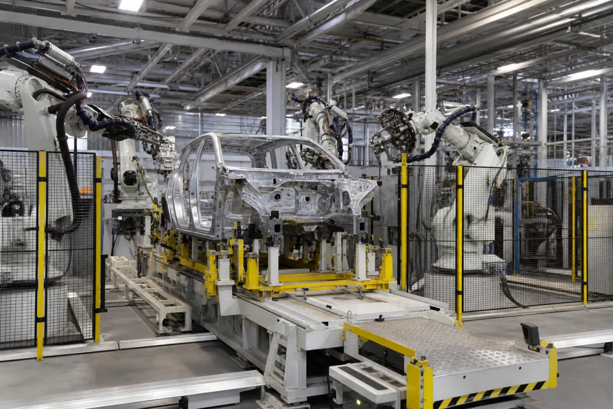
Representative product image. Confirm appearance and specifications with the manufacturer.

Product Specifications

Technical details and manufacturing context for Smart Robotic Body-in-White Assembly System

Definition
The Smart Robotic Body-in-White Assembly System is an integrated robotic solution designed for constructing complete vehicle body structures, commonly referred to as Body-in-White (BIW). This industrial-grade system coordinates multiple robotic workstations to perform precise joining operations, including spot welding, laser welding, and adhesive bonding. It features synchronized material handling, real-time quality monitoring, and adaptive programming to support mixed-model production. The system is intended as a turnkey solution for automotive body manufacturing facilities seeking high-volume, high-precision assembly capabilities. It handles materials such as high-strength steel, aluminum alloy, and advanced high-strength steel. Key parameters include 6–12 coordinated robotic stations, a maximum workpiece size of 5000×2000×1500 mm, a welding capacity of 60–120 spots per hour, system power consumption of 80–150 kW, and a floor space requirement of 300–600 m². Positioning accuracy is ±0.1 mm, repeatability is ±0.05 mm (per ISO 9283), and cycle time per station is 45–90 seconds. Each robot has a rated load capacity of 150–300 kg (ISO 9283). Operating temperature range is 0–45 °C, supply voltage is 380–480 V AC (three-phase, 50/60 Hz, per IEC 60038), and compressed air consumption is 1.5–3.0 m³/min at 0.6 MPa (ISO 8573-1). Control system communication protocols include PROFINET and EtherNet/IP (IEC 61158), and the safety category is PL d, Category 3 (ISO 13849-1). These values are reference ranges for directory purposes; verify model-specific specifications and standards with the legal manufacturer or supplier before procurement.
Working Principle
Multiple industrial robots equipped with specialized end-effectors perform coordinated assembly operations on body panels and structural components. The robots are guided by 3D vision systems that locate parts and verify weld positions. A central programmable logic controller (PLC) synchronizes all stations along the production line, managing the sequence of operations, material handling, and quality checks. The system adapts to different vehicle models through programmable logic and tooling changes, enabling mixed-model production. Real-time monitoring provides feedback for process control and maintenance alerts.
Common Materials
High-Strength Steel, Aluminum Alloy, Advanced High-Strength Steel
Technical Parameters
ParameterTypical rangeNotes & selection driver
Number of Robotic StationsRequired6–12 unitsTotal number of coordinated robotic workstations in the system
Maximum Workpiece SizeRequired5000×2000×1500 mmLargest vehicle body dimension the system can accommodate
Welding CapacityRequired60–120 spots/hourMaximum number of spot welds the system can perform per hour
System Power ConsumptionRequired80–150 kWTotal electrical power required for full system operation
Floor Space RequirementRequired300–600 Total area required for system installation including safety zones
Positioning Accuracy±0.1 mmFor robot end-effector repeatabilityISO 9283
Repeatability±0.05 mmEnsures consistent weld placementISO 9283
Cycle Time per Station45–90 sFor typical body-in-white assembly operations
Rated Load Capacity per Robot150–300 kgFor handling heavy assemblies and welding gunsISO 9283
Operating Temperature Range0–45 °CFor robot controllers and servo drives
Supply Voltage380–480 V ACThree-phase, 50/60 HzIEC 60038
Compressed Air Consumption1.5–3.0 m³/minAt 0.6 MPa supply pressureISO 8573-1
Control System Communication ProtocolPROFINET, EtherNet/IPFor integration with MES and PLCIEC 61158
Safety CategoryPL d, Category 3Per safety-rated monitored stop and interlocksISO 13849-1

Ranges are indicative industry figures for RFQ preparation, not a supplier commitment. Confirm every value and standard with the legal manufacturer before ordering.

Components / BOM
  • Articulated Industrial Robots
    Perform precise assembly, welding, and handling operations
    Material: Cast aluminum and steel construction
  • Central Control System
    Coordinates all robotic movements and process synchronization
    Material: Industrial-grade electronics enclosure
  • 3D Vision Guidance System
    Provides real-time positioning feedback and quality inspection
    Material: Stainless steel housing with optical components
  • Welding Power Supplies
    Delivers precise electrical current for resistance spot welding
    Material: Copper windings and steel casing
  • Material Handling Conveyors
    Transports body components between assembly stations
    Material: Steel frame with polymer belts
  • Safety Light Curtains
    Creates protective barriers around robotic work envelopes
    Material: Aluminum housing with infrared emitters

Industry Taxonomies & Aliases

Commonly used trade names and technical identifiers for Smart Robotic Body-in-White Assembly System.

Industrial Ecosystem & Supply Chain Structure

Complementary Systems
Downstream Applications
Specialized Tooling

Application Fit & Sizing Matrix

Operational Limits
pressure: N/A (pneumatic systems: 0.5-0.8 MPa)
other spec: Payload capacity: 50-500 kg, Positioning accuracy: ±0.1 mm, Cycle time: 30-120 seconds per station
temperature: 15-35°C (operating environment)
Media Compatibility
✓ Automotive steel sheets (0.6-2.0 mm thickness) ✓ Aluminum alloy body panels ✓ Structural adhesives and sealants
Unsuitable: Corrosive chemical processing environments (e.g., acid baths, salt spray testing areas)
Sizing Data Required
  • Vehicle body dimensions and annual production volume
  • Number of welding/joining points per body
  • Required automation level (full vs. semi-automated integration)

Reliability & Engineering Risk Analysis

Failure Mode & Root Cause
Servo Motor Overheating
Cause: Excessive duty cycles or inadequate cooling leading to thermal degradation of windings and bearings
Precision Bearing Wear
Cause: Contaminant ingress (metal shavings, dust) or misalignment causing accelerated fatigue and loss of positional accuracy
Maintenance Indicators
  • Abnormal high-pitched whining or grinding from servo motors or gearboxes
  • Visible misalignment or drift in robotic arm positioning during repetitive welding/assembly cycles
Engineering Tips
  • Implement predictive maintenance using vibration analysis and thermal imaging to detect early bearing/motor degradation
  • Establish strict contamination control protocols with regular filter changes and sealed environments for critical motion components

Indicative industry ranges for design and RFQ preparation. Confirm the exact figures and applicable standard with the manufacturer before specifying.

Compliance & Manufacturing Standards

Applicable Standards
ISO 10218-1:2011 - Robots and robotic devices - Safety requirements for industrial robots ANSI/RIA R15.06 - Industrial Robots and Robot Systems - Safety Requirements CE Marking - Machinery Directive 2006/42/EC

Quoted from the published standard.

Manufacturing Precision
  • Positioning Accuracy: +/-0.05mm
  • Repeatability: +/-0.02mm
Quality Inspection
  • Laser Tracker Metrology for Dimensional Verification
  • Functional Safety Test (PL/SIL Assessment)

Manufacturers of Smart Robotic Body-in-White Assembly System

Manufacturer profiles associated with Smart Robotic Body-in-White Assembly System.

Sourcing Smart Robotic Body-in-White Assembly System from China?
Tell us your specification and target quantity — we will match it against manufacturer records and come back with the factories that fit.
Request manufacturers We manufacture this

Manufacturer listings support early research and capability understanding. They are not certification, ranking, or transaction guarantees.

Technical documentation
Request current drawings, revision history, and a signed specification sheet.
Manufacturing capability
Verify equipment lists, process limits, capacity, and representative production evidence.
Inspection readiness
Confirm test methods, calibrated equipment, sampling plans, and traceable reports.
Supplier transparency
Check the legal entity, factory address, ownership, certifications, and direct contacts.

CNFX does not score or rank suppliers. Buyers must verify all claims and documents with the legal manufacturer before ordering.

Frequently Asked Questions

What joining processes does the system support?

The system supports spot welding, laser welding, and adhesive bonding, as described in the product definition. These processes are performed by robotic workstations with specialized end-effectors.

What materials can the system handle?

The system is designed to work with high-strength steel, aluminum alloy, and advanced high-strength steel, as listed in the product specifications. Material compatibility should be confirmed with the manufacturer for specific applications.

What are the key performance parameters?

Key parameters include a welding capacity of 60–120 spots per hour, a cycle time per station of 45–90 seconds, positioning accuracy of ±0.1 mm, and repeatability of ±0.05 mm (ISO 9283). These are reference ranges; verify actual values for your model.

What communication protocols are supported?

The control system supports PROFINET and EtherNet/IP, per IEC 61158. These protocols facilitate integration with MES and PLC systems. Confirm compatibility with your existing infrastructure.

Data Basis

Editorial classification, named public sources where available, and source-reviewed manufacturer records.

Preliminary Technical Classification
This page supports structured research, RFQ preparation, and supplier evaluation. It does not replace buyer-led supplier qualification, standards review, or technical approval.
Buyer enquiry

Request manufacturing insight for Smart Robotic Body-in-White Assembly System

Ask for use case, specification boundaries, supplier type, and RFQ preparation information for this product.

Where it goes
Straight to the CNFX editorial desk, and to the manufacturer if this product is linked to a claimed profile. Nothing is broadcast to a supplier list.
Your details stay here
We do not sell or rent enquiry data, and we do not add you to a mailing list. Used only to answer this request.
No commission, no middleman
CNFX is a directory. We take no cut of any order and never negotiate on a supplier's behalf.
What we don't claim
A listing is not an endorsement. Qualify every supplier and verify every figure yourself before ordering.

Your business information is used only to process this request.

Thank you! Your message has been sent. We'll respond within 1–3 business days.
Sorry, we couldn't send your message. Please try again, or email us at contact@cnfx.com.

Need to Manufacture Smart Robotic Body-in-White Assembly System?

Compare manufacturer profiles with relevant product and process capability.

Get QuotesChat