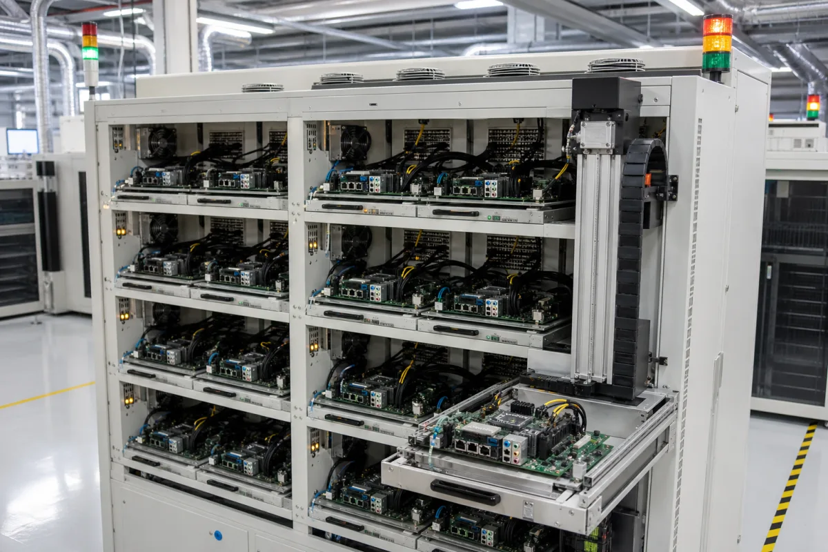
Motherboard burn-in rack: powered run-in of assembled boards in drawers
Board run-in racks · Drawers of powered motherboards, raised ambient for days, stress software and loopback plugs on every port
A motherboard burn-in tester holds fully assembled computer or server boards in pull-out drawers, connects power and the board's own ports, and keeps every board running diagnostic load for a set time at a raised ambient temperature. Faulty boards are logged per slot and pulled; the rest ship. What has to be specified is the ambient and duration, what the boards run while they sit there, and how the rack loads, powers and records each slot.
Racks, carts and burn-in rooms that hold assembled computer motherboards and server boards in drawers or trays, power them and run functional load for hours to days at a raised ambient, including automated drawer loading, per-slot power and fault logging. Unlike a climatic chamber, the rack itself does not cycle temperature or humidity: temperature, temperature–humidity, thermal shock and stability chambers are covered on the Test chamber page, and low-pressure chambers on the Altitude test chamber page. Cleanroom air-handling units and vacuum outgassing apparatus, which share the same parent page, are covered on the Cleanroom conditioning system and Outgassing test sample chamber pages. Burn-in of bare ICs in sockets is outside this page.
CNFX editorial research · Sources checked October 12, 2026 · 4 sources
65 °C for one week: setting the run-in ambient and duration for assembled boards
A University of Chicago note for the ATLAS TileCal electronics proposed burning in fully assembled PC board systems for one week at an elevated ambient of 65 °C, to remove infant-mortality failures from board assembly and freak failures of individual parts. It estimated the infant-mortality lifetime at 5–20 hours and the freak lifetime at 1,000 hours, and chose 65 °C as close to the components' maximum operating temperature because die temperatures run well above ambient. [1]
Using an Arrhenius model with an activation energy of 1 eV, the note puts ageing at 65 °C at 100 times the rate at 25 °C, so the one-week run equals about 1.9 years of normal operation, and 17 times the estimated freak lifetime. It calls a one-week period typical of industrial procedures. [1]
Editorial calculation: with the same 1 eV and Boltzmann's constant of 8.617 × 10⁻⁵ eV/K, the factor from 25 °C (298.15 K) to 65 °C (338.15 K) is exp(11,605 × (1/298.15 − 1/338.15)) ≈ 100, confirming the note. Dropping the rack ambient to 45 °C gives ≈ 11.6, so a 168-hour run at 45 °C covers about 1,940 hours of 25 °C operation instead of about 16,800. The activation energy is the note's assumption, not a measured value for any board. [1]
The note also sets the repair rule: any failure is repaired and that board restarts the full week (a 'markovian' burn-in), repeated until it passes. Each motherboard assembly in that set-up carried 48 plug-in cards, with five assemblies giving 240 cards under test at once and a weekly changeover estimated at under a day. [1]
State the ambient setpoint the rack or room must hold, the run time per batch, whether a failed board restarts the full period, the board's own maximum operating temperature, and how many boards change over per shift.
02
Stress software on every board and loopback plugs in the rear I/O
Heat alone does not exercise a motherboard; the boards must run work. PassMark describes its BurnInTest software as stress-testing the CPU, memory, storage, network and ports, with test modules that run in parallel or singly and an adjustable duty cycle for each; running them in parallel raises system load and, in PassMark's words, shortens the burn-in period. Results come out as text or HTML with CPU and GPU temperatures and disk and memory serial numbers, and the tool can boot from a USB drive. [3]
Ports are exercised with plugs fitted in the drawer. PassMark's USB 3.0 loopback plug shows port voltage to ±0.1 V and can run data loopback at up to the 5 Gbit/s defined for USB 3.0, though PassMark adds that in its testing few PCs reached much above 3.5 Gbit/s, with results depending on the motherboard, CPU and other USB devices attached. Up to 32 plugs can be connected to one PC if ports and power allow, and a USB-C version covers ports up to 20 Gb/s. [4][3]
Editorial note: in a rack this becomes wiring work in every drawer, power plus the plugs and links each board's tests need. The University of Chicago set-up kept at least one assembly under continuous readout and logged the time and location of every failure; it found continuous logic tests on all systems impractical and retested each assembly after the week instead. [1]
List the board form factors and their rear I/O, which ports need loopback plugs, the test software and boot method, and the per-slot data (temperatures, serial numbers, pass/fail) the rack must record.
03
Steady powered burn-in versus thermal cycling of unpowered assemblies
Quanterion, summarising USAF Rome Laboratory starting-point guidance derived from DOD-HDBK-344, separates screens of bare printed wiring assemblies from screens of complete equipment. A motherboard rack runs boards powered at one temperature; the cycling screens below need a chamber that can ramp. [2]
Quanterion gives one comparison from its screening-strength model: a simple soak at 75 °C for 8 hours scores 1.59, while 20 cycles between −50 and 75 °C score 9.01, a 5.67-fold increase. It also cites Telcordia SR-332 Issue 1 as estimating a failure rate at initial deployment four times the rate reached after one year. [2]
Editorial note: the two approaches answer different questions. A powered rack finds boards that fail while running real code at a raised ambient; a cycling chamber stresses solder joints and parts with temperature swings but, at assembly level in this guidance, without power. Buyers who want both specify the rack for run-in and a separate chamber, covered on the Test chamber page, for cycling.
Paste it into your enquiry below or into an email to a maker, then replace every bracket.
Boards: [form factor; size; rear I/O; power draw per board]
Capacity: [drawers per rack; boards per drawer; racks]
Ambient: [setpoint; tolerance; room or enclosed rack]
Run: [hours per batch; restart rule after a repair]
Load: [test software; boot method; loopback plugs per port type]
Loading: [manual drawers or automated loader]
Records: [per-slot log; temperatures; serial numbers; MES link]
Explore company information and manufacturing capabilities, then discuss the scope of your project with a relevant supplier.
Share this page
Compiled and source-reviewed by the CNFX editorial team.
Each manufacturer above links to the page on that company's own website where the product is listed, with the date we checked it. How we source and review
· Page last updated 13 October 2026
Buyer questions
How long and how hot is a board burn-in?
One published example, a University of Chicago plan for assembled boards, used one week at a 65 °C ambient, which it equated to about 1.9 years at 25 °C using a 1 eV activation energy. [1]
What runs on the motherboards during burn-in?
Stress software exercising CPU, memory, storage, network and ports, such as PassMark BurnInTest, with loopback plugs fitted to USB and other ports. [3][4]
Is a burn-in rack the same as thermal cycling?
No. Rome Laboratory guidance summarised by Quanterion cycles bare assemblies unpowered from −50 to +75 °C for 20–40 cycles; a burn-in rack keeps boards powered at one ambient. [2]
Why is the ambient kept below the board's limit?
Die temperatures exceed ambient, so the University of Chicago note set 65 °C close to the components' maximum operating temperature. [1]
Sources and what still needs a direct check
Sources checked 2026-10-12. The duration and temperature example is a 1999 University of Chicago engineering note for physics detector boards, not a computer maker's procedure. The screen comparison is Quanterion's summary of US Air Force guidance; the software and loopback details are from PassMark's own product pages.