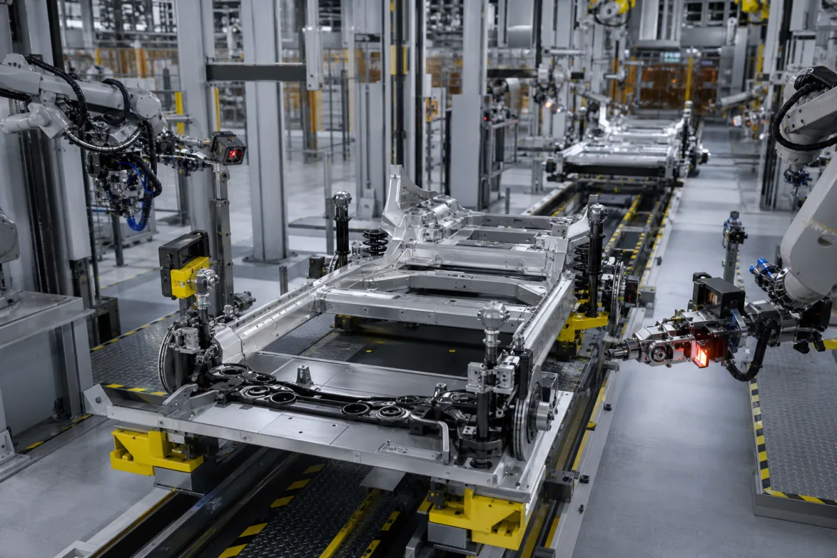
Chassis rigging and marriage line: building the axle and drive module on an assembly frame and joining it to the body
Final-assembly chassis line · axles, drive unit and battery rigged on an assembly frame, coupled to the body at the marriage station, then bolted with high-torque spindles under torque-and-angle control
In the final-assembly layout a line builder such as ROFA describes, the chassis is not built on the body. Its parts — front and rear axle, engine or electric drive, tank, exhaust, high-voltage battery — are first rigged on an assembly frame that travels as a pallet, checked, and only then raised into the body, which hangs above on an overhead conveyor. That joining step, the marriage, is followed by joints that one nutrunner maker calls the highest-torque, highest-consequence tightening in final assembly. This page follows the chassis from rigging to the last bolt, using a line builder's description, a lift maker's marriage-station project and a nutrunner maker's chassis-bolting installation.
Chassis rigging and marriage lines in vehicle final assembly: assembly frames or pallets carrying axles, drive units, tanks, exhausts and batteries, the conveyors and lifts that bring them under the body, the coupling and the automatic or worker-guided chassis bolting that follows. Individual assembly robots and their sizing are covered on the Assembly robot page, nutrunner torque control itself on the Fixtured electric nutrunner torque control system page, and overhead body conveyors on the Overhead power-and-free conveyor page; household-appliance lines are on the Automated refrigerator assembly line and Automated dishwasher production line pages. Body-in-white welding, paint shops, wheel alignment and end-of-line testing are outside this page.
CNFX editorial research · Sources checked October 12, 2026 · 4 sources
From rigging section to marriage: what travels on the assembly frame and how it reaches the body
ROFA (Moll Automatisierung) describes the sequence as three linked sections. In the rigging section, front and rear axles, engine, tank, exhaust system and battery are mounted on an assembly frame used as a pallet. Connecting material handling then carries the frame to chassis installation, where the chassis is coupled to the body, screwed, and the frame uncoupled. [1]
ROFA notes that the stations are passed through in cycles, and that continuous production is also possible, for example with automated guided vehicles. [1] Its robot cells for screwing and handling rear axles and high-voltage batteries use robots from about 20 kg to about 1,300 kg load capacity, with multiple robots integrated in one cell. [2]
Editorial note: because the buffer between rigging and installation is the line's only decoupling point, its length decides how long a rigging fault can be cleared without stopping the marriage; ask the builder to state the buffer in frames and in minutes at line rate.
Section
Equipment named by ROFA
Engine line
Engine pallet for motor and transmission; screwing devices, for example for the drive shaft; floor or ceiling electric monorail; cranes with load-handling devices for engine, transmission or generator [1]
Rigging section
Assembly frame as pallet; roller, chain or monorail conveyor; screwing devices for front and rear axle; testing station with camera placement inspection [1]
Connecting handling
Roller and toothed-chain conveyors, self-driving and traversing cars, eccentric lifting tables, lifting stations, swivelling tables, turntables and transfer stations; doubles as a buffer of variable length, over more than one level if needed [1]
Chassis installation
Body hanging in a load-handling device on an electric monorail or power-and-free conveyor; gross coupling then fine coupling; automatic screwing by NC axes or robots, or worker-guided screwing; worker platforms; uncoupling [1]
02
A marriage lift that reaches out for the axle: 3,080 lb, 14 in of travel and a 1.5 m slide
Handling Specialty's Specialty Solution 68 is a custom mechanical cantilevered lift built for an automotive assembly-line integrator and installed in a marriage station in a North American plant. [3]
The sequence: the slide extends 1.5 m and picks up the axle while shot pins hold the platform rigid; it indexes back over the lift centreline, the pins release, and as the lift rises about 10 in, springs on the lift compress and the axle is fixed into the vehicle. [3] The maker describes the operation as smooth with zero drift. [3]
Editorial calculation: 3,080 lb is about 1,397 kg, and 14 in of travel is about 356 mm; a 10 in rise is about 254 mm of the stroke.
Four air cylinders with locking pins; shot pins lock top to base while the slide is cantilevered [3]
03
Chassis bolting after the marriage: 130–1,000 N·m, torque plus angle, every joint recorded
Leetx describes an installation at a commercial-vehicle maker in south-west China (light and micro trucks and new-energy models, mixed on one line) where the wheel and chassis tightening stations were switched from pneumatic to electric tools. It calls wheel and chassis tightening — front suspension, rear suspension, axle-hub nuts — the operations with the highest safety level and torque requirements in final assembly. [4]
ROFA's description of the marriage station distinguishes the same split: under the vehicle, NC axes or robots with EC screwdrivers, or automatic screwing devices; elsewhere, worker-guided screwing from platforms. [1] A buyer should list every chassis joint with its torque, angle window and whether it is automatic or manual, since that list sets the number of spindles, their torque class and the reaction-arm points on the platforms.
Editorial calculation: 1,000 N·m is about 738 lbf·ft, and the 130–1,000 N·m range spans a factor of about 7.7 between its ends.
Station
What Leetx states
Chassis tightening
Torque range 130–1,000 N·m; torque plus angle control; automatic stations bus-controlled with parameters collected in real time [4]
Manual chassis points
High-torque mechanical reaction arm; angle-head wrench or straight spindle depending on access [4]
Wheel nuts
One machine with six spindles; for 5-nut models five spindles move to the matching pitch circle and the sixth is disabled, without stopping the line [4]
Records
Torque and angle of every fastener collected and traceable [4]
Ask the line builder which joints are tightened by fixed spindles, which by robot-held tools and which by hand, and how the torque and angle record is tied to the vehicle identification number.
04
Data for a chassis rigging and marriage line enquiry
Paste it into your enquiry below or into an email to a maker, then replace every bracket.
Vehicles: [models; mixed-model ratio; wheelbase and track range; drive types]
Rate: [jobs per hour; shifts]
Rigging: [components on the frame; frame or AGV; buffer length]
Marriage: [body conveyor type; lift capacity and travel; coupling method]
Bolting: [joint list with torque and angle windows; automatic or manual per joint; record format]
Battery: [mass; fastener count; handling robot payload]
Safety: [worker platforms; access to manual points]
Explore company information and manufacturing capabilities, then discuss the scope of your project with a relevant supplier.
Share this page
Compiled and source-reviewed by the CNFX editorial team.
Each manufacturer above links to the page on that company's own website where the product is listed, with the date we checked it. How we source and review
· Page last updated 13 October 2026
Buyer questions
What is a marriage station?
The point in final assembly where the rigged chassis on its assembly frame is raised into the body, coupled (gross then fine) and screwed, before the frame is uncoupled, as ROFA describes it. [1]
How heavy a load does a marriage lift carry?
Handling Specialty's marriage-station lift is rated 3,080 lb with 14 in of travel and a slide that reaches out 1.5 m to collect the axle. [3]
What torque do chassis bolts need?
In Leetx's commercial-vehicle installation, chassis tightening covers 130–1,000 N·m with torque plus angle control. [4]
How big are the robots that handle batteries and axles?
ROFA's screwing and handling cells use robots from about 20 kg to about 1,300 kg load capacity. [2]
Sources and what still needs a direct check
Sources checked 2026-10-12. Line sequence and equipment from ROFA (Moll Automatisierung) pages on marriage stations and robot stations; lift data from Handling Specialty's solution sheet 68; chassis bolting data from a Leetx installation report (in Chinese).