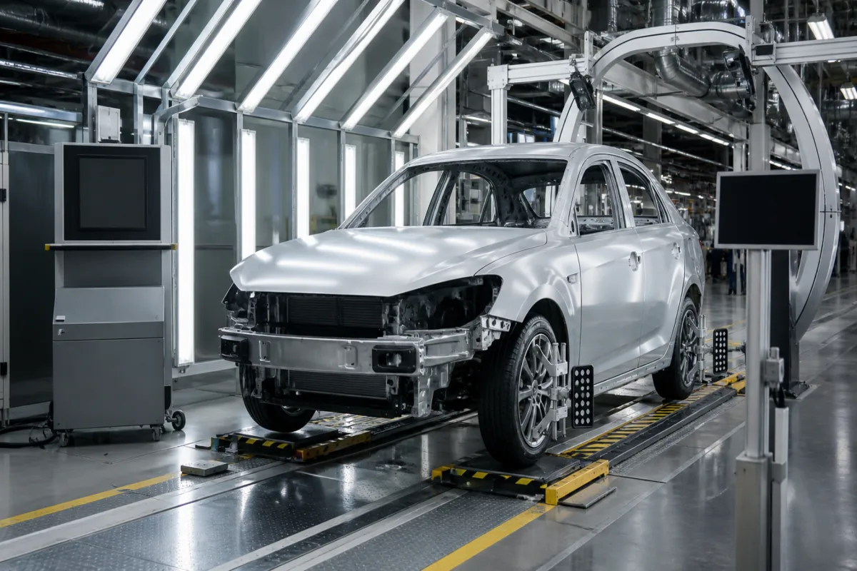
End-of-line wheel alignment and headlamp aiming station for passenger cars: toe and camber on the finished car, stand calibration and dipped-beam aim
The end-of-line stand where a finished car's toe and camber are measured and set and its dipped-beam headlamps are aimed · why static measurement on the finished car errs by the hub's wobble, Honda's two ways of moving alignment upstream, a rolling master calibrated on a CMM to compare stands, and UN R48's −1.0 to −1.5 % initial headlamp aim
At the end of an assembly line the car rolls onto a stand where wheel targets or sensors read toe and camber, the alignment is adjusted to the specification, and the headlamps are aimed to the inclination marked on the car. Three questions decide whether that station delivers: how the measurement handles a wheel and hub that are never perfectly true, how one stand is kept in agreement with the next, and what aim the headlamps must be set to.
End-of-line test and setting stands in passenger car assembly plants that measure and adjust wheel alignment (toe and camber) and aim dipped-beam headlamps, and in-line alternatives that measure alignment before wheels are fitted. Camera, lens and lighting selection for production-line vision is covered on the Machine vision system for inspection page; multi-camera stations for cast and machined parts on the Vision system for cast and machined parts page. Roller brake testers, ADAS sensor calibration and paint inspection tunnels are outside this page.
CNFX editorial research · Sources checked October 13, 2026 · 4 sources
Toe and camber on the finished car: hub runout, tyre lettering and line flow
Honda's European patent EP 1 352 209 B1 sets out the problems with the method it cites from JP-A-60-001509, in which the wheel of the completed car is sandwiched between detection plates and sensors read their displacement: the measurement is done along with the other end-of-line checks, so the number of items is large and the flow of the line may be held up; positioning the wheel precisely between the plates takes labour; raised lettering on the tyre sidewall puts an error into the reading; and the plates need stays and a linkage to move them together. [1]
The patent adds an error from the hub itself: depending on the manufacturing accuracy of the hub and its shaft, a rotating wheel oscillates by +α and −α about its true inclination θ, so the toe angle varies sinusoidally between θ+α and θ−α, and a static measurement can be off by α. Honda's answer is to measure before the wheel is fitted: a disc pressed on the hub bolt tips rotates with the hub while displacement sensors read its side face, which cancels errors from uneven bolt lengths and lets a plurality of wheels be measured from the sides of a moving car. [1]
A second Honda patent, EP 1 512 941 B1, measures toe and camber with the body still on its hanger. Wheel mounts lift the suspension from −90 mm below its running position to the adjusting position at −60 mm, measuring every 10 mm; the change of toe and camber with height is extrapolated to the running position at 0 mm, and the adjustment is calculated for −60 mm. The 30 mm lift does not raise the body off the hanger. [2]
Editorial note: both patents move part of the work upstream of the end-of-line stand; a final stand on the finished car still sees the car as the customer will drive it, which is why the questions above apply to any stand offered. [1][2]
Ask how the stand removes hub and rim runout from the reading (rotation, multiple readings or averaging), how tyre sidewall lettering is handled, and the cycle time per car.
02
Keeping stands in agreement: a rolling master calibrated on a CMM
Dürr describes its x-wheel stand for passenger cars with non-contact three-dimensional measuring systems, x-3Dprofile and the area-based x-3Dsurface, and steering wheel balancers that measure the steering wheel angle. [3]
To check the measurement process Dürr uses a rolling master with known toe and camber values, different but fixed values for each tyre rim, and fixed height measurement surfaces at the wheel arch. It is calibrated on a coordinate measuring machine and supplied with a test certificate, and is used to determine process capability indices and machine capability independently of the car, and to match two or more stands with each other. [3]
Ask for the stand's machine capability result on a calibrated master and how two stands in the same plant are matched.
03
Aiming the dipped beam to UN R48: −1.0 to −1.5 % below 1.0 m
UN Regulation No. 48 on installation of lighting devices requires the manufacturer to specify the initial downward inclination of the dipped-beam cut-off, set in the unladen vehicle with one person in the driver's seat, to within 0.1 per cent, and to mark it on each vehicle near a headlamp or the manufacturer's plate with the symbol in its Annex 7. [4]
Where a headlamp sits on a movable component, the regulation checks repeatability by moving it to its normal position 10 times; no inclination may differ by more than 0.15 per cent from the average of the 10 readings, and any excess narrows the allowed range. Where a levelling device is needed to meet the limits it has to be automatic, with manual devices allowed only if they have a stop position returning the lamps to the initial inclination. [4]
Editorial calculation: an inclination of −1.0 % drops the cut-off 100 mm over 10 m and −1.5 % drops it 150 mm, so the 0.5-point initial-aim window for lamps below 1.0 m is 50 mm at 10 m; the 0.1 % marking accuracy is 10 mm at the same distance.
Explore company information and manufacturing capabilities, then discuss the scope of your project with a relevant supplier.
Share this page
Compiled and source-reviewed by the CNFX editorial team.
Each manufacturer above links to the page on that company's own website where the product is listed, with the date we checked it. How we source and review
· Page last updated 13 October 2026
Buyer questions
Why can static toe measurement on a finished car be wrong?
Honda's EP 1 352 209 explains that hub and shaft tolerances make a rotating wheel oscillate by ±α about its true angle, so a single static reading can be off by α. [1]
Can wheel alignment be measured before the wheels are fitted?
Yes; Honda patents measure hub inclination from a disc on the hub bolts, or toe and camber on the body hanger while lifting the wheel mounts from −90 to −60 mm. [1][2]
How are alignment stands checked?
Dürr uses a rolling master with fixed, known toe and camber, calibrated on a coordinate measuring machine, to determine machine capability and match stands. [3]
What initial headlamp aim does UN R48 require?
For a lamp lower edge below 1.0 m, the initial aim is between −1.0 % and −1.5 %, with limits of −0.5 % to −2.5 %, marked on the vehicle to 0.1 %. [4]
Sources and what still needs a direct check
Sources checked 2026-10-13. Alignment measurement problems and upstream alternatives come from two Honda European patents; stand calibration from Dürr's product page; headlamp aim from UN Regulation No. 48 as hosted by Japan's Ministry of Land, Infrastructure, Transport and Tourism.