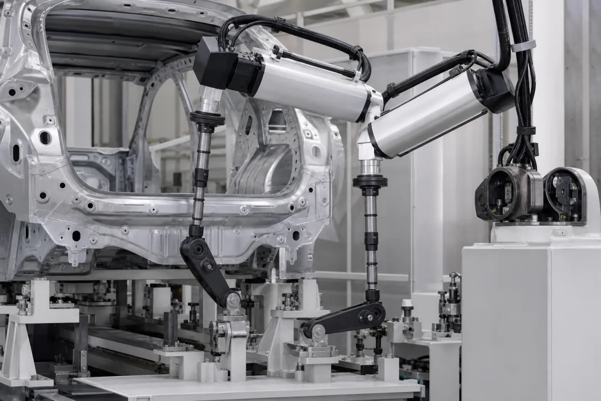
Fixtured electric nutrunner torque control system for vehicle and powertrain assembly
Fixtured electric nutrunner systems · Torque, torque-angle and yield-controlled strategies, preload scatter, tightening factor and spindle ranges for vehicle assembly
A fixtured nutrunner torque control system tightens bolts on an assembly line with electric spindles mounted in a fixture or on an arm: each spindle carries a torque transducer and angle sensor, and a controller runs the tightening strategy, records the result and rejects joints outside limits. Ask three things first: which strategy each joint needs (torque, torque-angle or yield), what preload scatter that strategy leaves, and what torque range and measuring equipment each spindle carries.
Transducerised electric nutrunner spindles and their controllers used in fixtures, multi-spindle heads and articulated arms on vehicle body, powertrain and chassis assembly lines, specified by tightening strategy, torque range and measurement. Hand torque wrenches, with their ISO 6789 types and classes, are covered on the Torque wrench page. Hydraulic torque wrenches, oilfield power tongs, impact wrenches and torque testers are outside this page.
CNFX editorial research · Sources checked October 12, 2026 · 3 sources
Pick the tightening strategy by the preload scatter it leaves
NASA's Fastener Design Manual (RP-1228, 1990) reproduces a Machine Design table of control accuracies, as preload accuracy: torque control ±15 to ±30%, turn control ±15 to ±30%, torque and turn ±10 to ±25%, torque past yield ±3 to ±10%, and bolt stretch ±1 to ±8%. The same table lists computer-controlled tensioning by simultaneous torque and turn at ±0.5 to 2% of full scale as a tool accuracy. [1]
The manual explains why the tool's accuracy is not the joint's: for T = K·F·d it warns that an assumed nut factor K = 0.2 should not be used blindly and gives 0.15 as a more realistic typical value for steel on steel, so preload follows friction. [1] Editorial calculation: an M12 bolt (d = 12 mm) needing 40 kN needs T = 0.15 × 40,000 × 0.012 = 72 Nm at K = 0.15, but 96 Nm at K = 0.2; the same 72 Nm on a joint whose K is really 0.2 gives only 30 kN. The bolt and preload are assumed examples. [1]
Würth's technical handbook gives VDI 2230 reference values for the tightening factor αA, the ratio of maximum to minimum assembly preload: 1.4 to 1.6 (±17% to ±23%) for torque-controlled tightening with targets found by elongation tests on the original part; 1.6 to 2.0 or 1.7 to 2.5 (±23% to ±43%, by friction class) when targets come from estimated friction; and 1.2 to 1.4 (±9% to ±17%) for yield-strength- or rotation-angle-controlled tightening, power-operated or manual. For these last two it notes that preload scatter is set by the yield point of the screw batch, so screws are dimensioned for minimum preload. [2]
Give the supplier each joint's bolt size and grade, target torque or preload and its tolerance, the strategy (torque, torque-angle, yield), snug torque and angle window, the number of spindles and their pitch, access and reaction, cycle time, the data to be stored per joint, the line controller interface, and the quality requirements the joints are classified under.
02
Size the spindle range and its measurement
Desoutter's EFDO60-680 offset fixtured spindle is listed for 60 to 680 Nm, for single or multiple synchronised spindles, with a built-in torque transducer and high-frequency angle sensor, 300° cable rotation and an optional IP54 kit. [3]
Editorial calculation: the 72 Nm M12 example sits at 72 ÷ 680 ≈ 11% of that spindle's top torque, near the bottom of its 60–680 Nm range; a smaller spindle would put the target higher in its range, where a full-scale accuracy figure is a smaller share of the reading. For example, ±1% of 680 Nm is ±6.8 Nm, about ±9.4% of a 72 Nm target. The ±1% is an assumed accuracy for illustration, inside NASA's ±0.5–2% band. [3][1]
Editorial note: angle-controlled and yield-controlled strategies need the angle sensor as well as the transducer. Ask whether each spindle has a redundant (second) transducer for safety-critical joints and how the controller checks the two against each other.
03
Torque, angle, torque-and-turn, yield and stretch: scatter and tightening factor side by side
Values as stated in the sources; tool accuracy and joint preload scatter are different quantities.
Nutrunner system quotation: torque range, accuracy basis, angle sensing and data interface
Ask for torque accuracy together with its sigma basis and test standard, because NASA's ±0.5–2% figure is of full scale and a target low in the range carries a larger share of it.
Explore company information and manufacturing capabilities, then discuss the scope of your project with a relevant supplier.
Share this page
Compiled and source-reviewed by the CNFX editorial team.
Each manufacturer above links to the page on that company's own website where the product is listed, with the date we checked it. How we source and review
· Page last updated 13 October 2026
Buyer questions
How much does preload vary under torque control?
NASA's Fastener Design Manual lists ±15 to ±30% for torque control, against ±3 to ±10% for torque past yield and ±1 to ±8% for bolt stretch. [1]
What tightening factor applies to angle or yield control?
Würth's VDI 2230-based table gives αA = 1.2 to 1.4 for rotation-angle and yield-strength-controlled tightening, against 1.4 to 1.6 for torque control with tested targets. [2]
What torque range does a fixtured spindle cover?
Desoutter lists its EFDO60-680 offset spindle for 60 to 680 Nm, with a torque transducer and angle sensor. [3]
Sources and what still needs a direct check
Sources checked 2026-10-12. NASA's Fastener Design Manual is US government guidance; Würth's handbook chapter reproduces VDI 2230 reference values; Desoutter's page describes its own spindle.