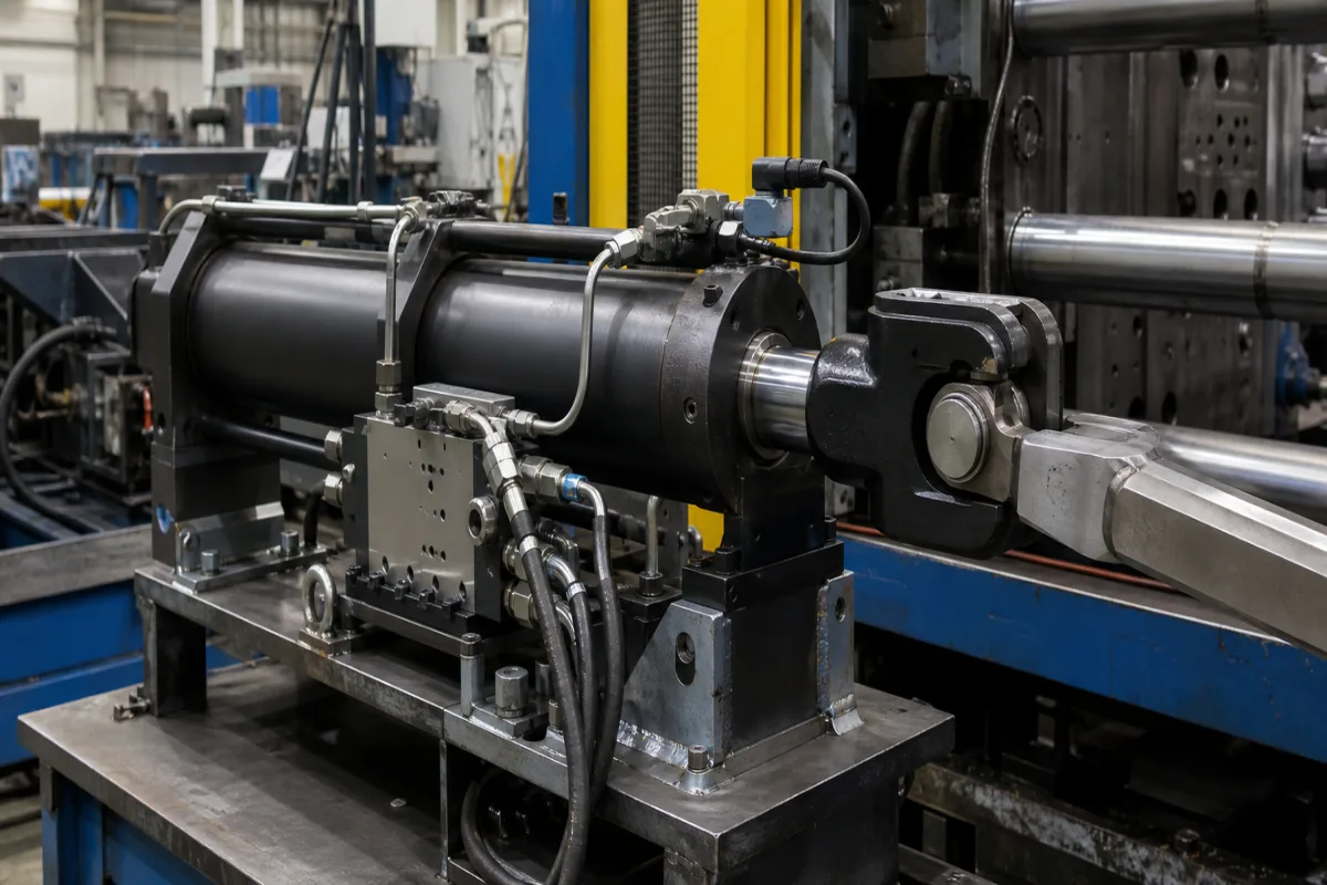
Valve-on-cylinder actuator assembly: a hydraulic servo cylinder with its control valve mounted on the barrel and a built-in position transducer
Hydraulic cylinder, control valve and position sensor bought as one unit · why the valve is mounted on the cylinder, valve size and response, and the bore, pressure and force of the cylinder
In this actuator assembly, the hydraulic cylinder, the control valve and the position transducer arrive as one closed-loop unit. The servo or proportional valve sits on a manifold plate on the cylinder barrel and feeds both ports through short drilled or tubed passages, and the transducer inside the cylinder reports rod position to the controller. The reason for building it this way is the oil between valve and piston: the less of it there is, and the shorter the path, the faster and stiffer the position loop can be. Buyers then size three things together: the cylinder's bore, rod and pressure for force, the valve's flow and response for speed, and the transducer and seals for the motion profile.
Linear hydraulic actuator assemblies for industrial machines and test rigs in which the control valve (servo or proportional, ISO 4401 subplate pattern) is mounted on the cylinder through a manifold or valve mounting plate, with an integrated position transducer and optional pressure or force sensors, supplied and tested as one unit. Quarter-turn pneumatic valve actuators are covered on the Pneumatic actuator page; ISO 5211 valve actuator mounting on the Valve actuator mounting page; air-over-oil intensifiers on the Hydro-pneumatic intensifier cylinder page; DC screw rod actuators on the Adjustment actuator page; and self-contained electro-hydraulic actuators for process valves and dampers on the Hydraulic actuator page. Mould oscillation servo units are covered on the Servo actuator unit for continuous casting mould oscillation page, rolling-mill cylinder transducers on the Position transducer page, and complete roll-gap control loops on the Heavy-duty rolling mill hydraulic gap control system page. Electromechanical servo press modules are covered on the Servo motor actuator for press-fitting page. Hydraulic power units and bare cylinders without valve or sensor are outside this page.
CNFX editorial research · Sources checked October 12, 2026 · 3 sources
Trapped oil and pressure-wave delay between the valve and the piston
Peter Nachtwey, writing in Hydraulics & Pneumatics, recommends mounting servo valves on the cylinder whenever possible, or as close to it as possible, because doing so maximises the natural frequency of the system by reducing its hydraulic capacitance and dead time. [1]
Capacitance is the change in volume divided by the change in pressure. With the valve on the cylinder, only the oil trapped between the valve and the piston counts; with hose in between, the hose's own expansion adds to it, and Nachtwey notes that hose makers publish little or no capacitance data. He gives the bulk modulus of oil as about 200,000 psi (1.35 × 10⁹ Pa), and in his natural-frequency estimate the trapped volume, and any hose capacitance, sit in the denominator, so added volume lowers it. [1]
Dead time is the delay before the piston starts to move after the spool does. Pressure changes travel at the speed of sound in oil, which he gives as about 1.2 m per millisecond (about 4 ft/ms). He cites a simulated water-slide ride built with 50 ft of hose between the control valves and the actuators, where the lag made a simple PID loop too difficult to tune. [1]
Editorial calculation: at 1.2 m/ms, 0.3 m of passage on a valve-on-cylinder manifold adds about 0.25 ms, 5 m of pipe about 4.2 ms, and the 50 ft (15.2 m) of hose about 12.7 ms. On volume, 5 m of hose with a 12.7 mm bore holds about 0.63 litres (π/4 × 0.0127² m² × 5 m), roughly as much as one chamber of a 100 mm bore cylinder at mid-stroke of a 200 mm stroke (π/4 × 0.1² m² × 0.1 m = 0.79 litres). Compressing 0.63 litres by 100 bar at 1.35 × 10⁹ Pa takes about 4.7 cm³ of extra oil (0.63 L × 10⁷ Pa ÷ 1.35 × 10⁹ Pa), before any hose expansion.
Ask the supplier for the oil volume between valve and piston at each end of stroke, and whether pressure transducers sit in the manifold or out on the line; Nachtwey argues for putting pressure sensors on the cylinder too. [1]
02
The valve on the plate: ISO 4401 size, rated flow per land and step response
Moog's D633 direct drive servo valve is a one-stage spool-and-bushing valve on an ISO 4401-03-03-0-05 mounting pattern, the size 03 subplate face that a valve mounting plate on the cylinder has to match. [2]
Moog explains that rated flow corresponds to 35 bar per land, 70 bar across two lands, and that mean flow velocity in the valve ports should not exceed about 30 m/s because of cavitation risk. The size 05 D634 is rated 60 or 100 l/min with a step response of 20 ms or less. [2]
Editorial calculation: 40 l/min into the 7,854 mm² piston area of a 100 mm bore is about 85 mm/s of extension (0.000667 m³/s ÷ 0.007854 m²), before any reduction for load pressure.
18/15/12 for functional safety; 17/14/11 for longer service life [2]
Give the speed you need at the load pressure you expect, so the supplier can choose the valve's rated flow and whether size 03 or 05 fits the cylinder's plate.
03
Cylinder bore, rod, pressure rating and force on the servo cylinder itself
Hänchen sells servo hydraulic actuators as single-rod or double-rod cylinders with an integrated position transducer and, as an option, a mounting plate for the control valve. [3]
The same page lists speeds up to 2 m/s, strokes from 1 to 1,500 mm, and a test pressure of 1.5 times the maximum working pressure. Hänchen states that its low-friction Servoseal seals in the slim series 120 and 300 serve test applications at frequencies up to 25 Hz, and it lists inductive proximity switches for end positions, force transducers on the rod, and chamber pressure transducers for condition monitoring. [3]
Editorial calculation: the 117.8 kN figure equals 150 bar × π/4 × (100 mm)², or 15 MPa × 7,854 mm². On the same cylinder, the 88.4 kN F2 corresponds to the annulus left after the 50 mm rod.
State force in both directions, stroke, speed, frequency and amplitude of the motion profile, and the fluid, so the supplier can choose series, seal system and transducer.
04
Data for a valve-on-cylinder servo actuator
Paste it into your enquiry below or into an email to a maker, then replace every bracket.
Motion: [stroke; speed; acceleration; frequency and amplitude if oscillating]
Force: [extend and retract force; load mass; side load]
Cylinder: [single or double rod; bore and rod; mounting style; rod end]
Valve: [servo or proportional; ISO 4401 size; rated flow; supply pressure]
Sensors: [position transducer output; pressure transducers; end switches]
Fluid: [type; temperature; cleanliness class]
Test: [pressure test; leak test; frequency response record]
Explore company information and manufacturing capabilities, then discuss the scope of your project with a relevant supplier.
Share this page
Compiled and source-reviewed by the CNFX editorial team.
Each manufacturer above links to the page on that company's own website where the product is listed, with the date we checked it. How we source and review
· Page last updated 13 October 2026
Buyer questions
Why mount the control valve directly on the cylinder?
Nachtwey's reason: it leaves only the oil between valve and piston to compress and shortens the pressure-wave path, raising natural frequency and cutting dead time. [1]
How fast does a size 03 direct drive servo valve respond?
Moog states a step response of 12 ms or less for 0 to 100% stroke on the D633, measured at 140 bar, 32 mm²/s and 40 °C. [2]
What working pressures do servo cylinders come in?
Hänchen lists 150 bar for series 120, 160 bar for series 160 and 300 bar for series 300, each pressure-tested at 1.5 times its maximum. [3]
Sources and what still needs a direct check
Sources checked 2026-10-12. An engineering article by Peter Nachtwey (Hydraulics & Pneumatics), Moog's D633/D634 servo valve catalog (Rev. D, November 2024), and Herbert Hänchen GmbH's servo hydraulic actuator page.