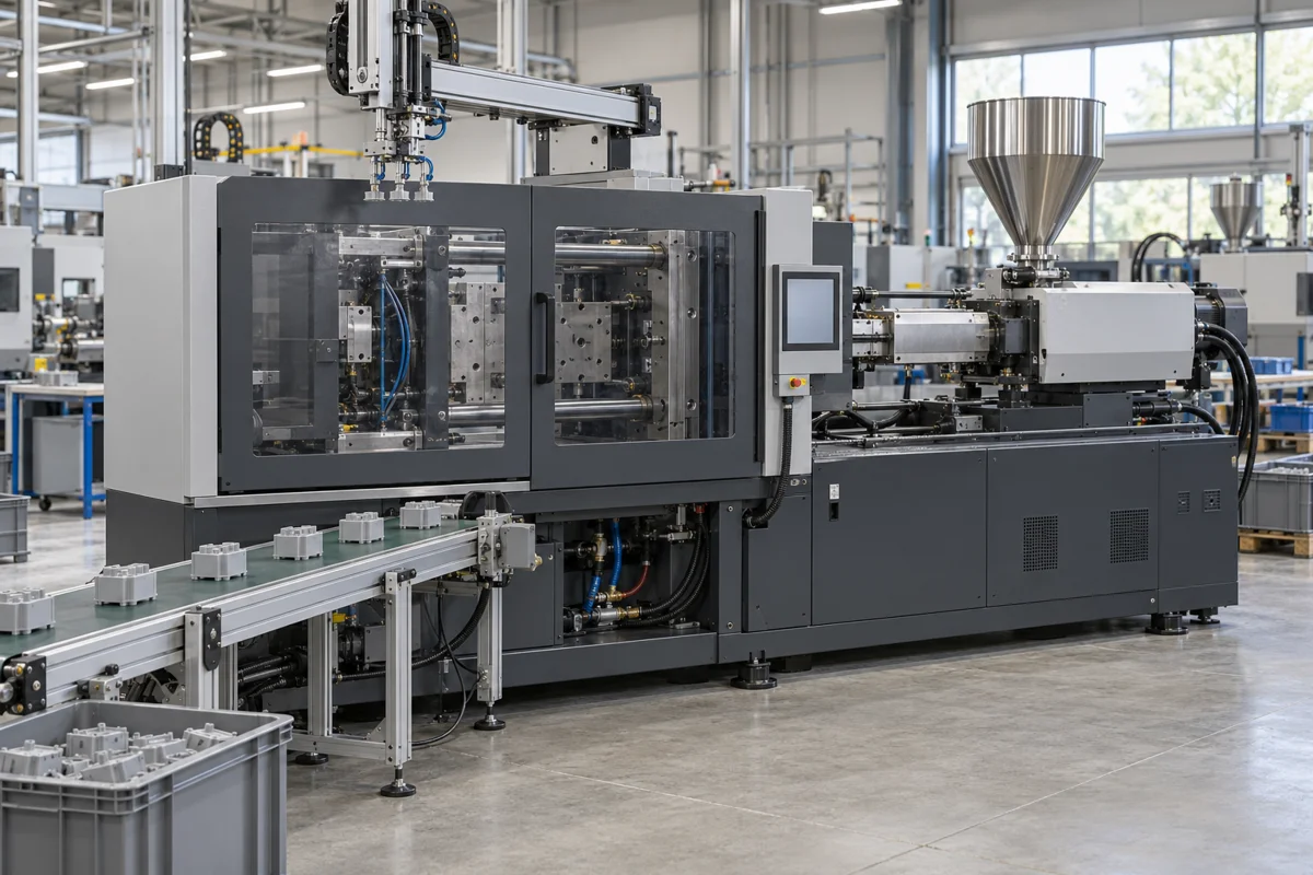
Start with the mold and resin. This guide works through clamp force and injection-unit sizing, then checks a servo-hydraulic toggle machine against the mold, robot and production cycle. Its reference numbers retain their material, model and test boundaries.
CNFX editorial research · Sources checked October 10, 2026 · 4 sources
Pellets enter the hopper; the screw prepares a metered melt charge, then advances to inject it through the nozzle. The clamp supports the closed mold during filling and holding. Mold cooling, opening and ejection must fit the rest of the cycle. Covestro explains the injection equipment; Tederic illustrates the toggle, injection carriage, hydraulic and control assemblies [1][2].
Assembly / part
Function and documented construction
Hopper, screw and barrel · injection unit
Feed, plasticize and meter the resin. Covestro distinguishes feed, compression and metering zones and shows a non-return valve. Screw geometry must suit the material and shot; no steel grade or coating is specified for a quoted NEO·T model in the reviewed brochure [1][2].
Non-return valve
The valve at the screw tip separates material preparation from forward injection. Covestro's screw diagrams show this part; a replacement requires the actual injection-unit drawing, diameter and valve design, not just the machine tonnage [1].
Heated nozzle and injection carriage
Deliver melt into the sprue bush and maintain nozzle contact. Covestro calls for separately controlled nozzle heating; Tederic describes twin carriage cylinders and linear guidance. Nozzle radius, aperture and alignment require a mold-interface drawing [1][2].
Platens, tie bars and toggle · clamping unit
Mount the mold, guide opening/closing and transmit clamp load. Tederic shows a box-type platen, toggle linkage and moving-platen support. Mold mass and mounting dimensions need a model-specific schedule; the public brochure supplies no manufacturing part numbers or material grades [2].
Ejection and mold services
Release the molded part and supply the agreed mold connections. Tederic lists ejector-plate monitoring and hot-runner integration among control features; the mold's ejector pattern, core pulls and required zones still need confirmation [2].
Servo-hydraulic drive · hydraulic system
Provide controlled hydraulic motion and pressure. The NEO·T brochure describes servo control, cylinders, piping and filtration. Its 17.5 MPa response claim concerns the hydraulic system, not melt injection pressure [2].
Controller, temperature and position feedback · control system
Coordinate motion and barrel-temperature control. Tederic names Techmation/KEBA controller configurations; the delivered controller, inputs, options and software must be listed in the order [3].
Mold temperature-control circuits
Remove or supply heat through the mold. Covestro treats pump capacity, flow resistance and separate circuits as process variables. These are installation services; confirm whether temperature-control units and connections are included with the machine [1].
This functional BOM explains the machine assemblies and the parts identified in the technical sources. Quantities, manufacturing part numbers, steel grades, seal materials and replacement compatibility require the supplied model drawings and parts list.
02
Calculate clamp force from every pressure-loaded area
Covestro's March 2016 guide gives minimum clamp force [kN] = projected area [cm²] × mean cavity pressure [bar] ÷ 100. The pressure is the mean pressure in the cavity—not the machine's maximum injection-pressure setting [1].
Project the whole load onto the parting plane
Include all cavities and pressure-loaded runners. For an annulus, A = π(D² − d²)/4; use consistent dimensions. A part's surface area or bounding-box area is not automatically its projected pressure-loaded area [1].
Keep the example's assumptions visible
Four PC parts with projected area 100 cm² each give 400 cm² before adding runner area. Assuming 400 bar mean cavity pressure, 400 × 400 / 100 = 1,600 kN, about 163 tonnes-force. This is CNFX arithmetic for the parts alone; runners and actual process conditions can increase the required force.
Check the mold and process before selecting a tonnage
Covestro explains that stiffness, permitted mold breathing, geometry and filling/holding conditions affect the practical requirement. Its material-family pressures are a starting reference, not a guaranteed pressure for every current grade or mold [1].
Prevent flash damage
The guide warns that flash can press into a large hardened mold's parting plane and require re-machining. Confirm the clamping requirement with the mold designer rather than treating a calculated minimum as the final machine selection [1].
300–700 bar; the guide notes higher values for very free-flowing grades to prevent flash [1]
03
A clamp that fits can still have the wrong injection unit
Covestro selects screw diameter against shot weight/volume, metering stroke and residence time. Its 2016 guide covers named engineering-plastic families; use the current resin grade's processing guidance for the actual purchase [1].
An oversized barrel can damage a small shot
A small shot in a large injection unit may use a short metering stroke and retain material longer. Covestro links that condition with degradation and color change. Select the injection unit for the shot and cycle even when a larger clamp is needed for mold dimensions [1].
Metering stroke
The guide recommends 1–3 screw diameters (D), with up to 4 D in exceptional cases. A stroke above 4 D can entrain air; a stroke below about 1 D raises residence-time and color/degradation concerns [1].
Mean permitted residence time
The guide gives 4–6 minutes for the discussed blends and flame-retardant grades, and 4–8 minutes for PC/PC-HT. It relates these limits to thermal sensitivity; below 4 minutes can also leave insufficient melt preparation, particularly for semi-crystalline materials. These are not universal limits for all polymers or temperatures [1].
Screw geometry
Its general screw figure shows length 18–22 D, feed zone 50–60% and compression zone 20–25%. Its text separately recommends 20–23 D three-zone screws for the named Covestro materials. Keep those scopes separate; the historical figure's EUROMAP reference does not establish current certification [1].
Larger screws and semi-crystalline materials
The guide calls for reduced flight depth above 80 mm for semi-crystalline resins. Confirm the screw drawing and resin application; a diameter alone does not define its geometry or plasticizing performance [1].
04
NEO·T's published ranges need a model-level answer
The sources do not agree on one range: Tederic's current NEO·T page shows a ≤1050 t badge and a 90–2200 t clamp-range table, while its linked brochure states 90–4000 t. Record the exact model and dated specification in the quotation; none of these labels proves which configuration is currently supplied [3][2].
Agree a production test rather than accepting a percentage alone
For the proposed mold, resin and stable cycle, agree the sample size, shot/part-weight measure, rejects and energy boundary. Record machine energy and auxiliary loads separately. EUROMAP's catalogue distinguishes machine-related and product-related energy recommendations; its titles do not supply a test result for NEO·T [4].
Injection repeatability · brochure claim
Less than 0.5%. The brochure does not define the statistic, sample count or test resin/mold. Do not silently rename this a witnessed shot-weight acceptance result [2].
Barrel temperature · brochure claim
≤ ±1 °C. This is barrel-temperature control, not a measured cavity-temperature uniformity or finished-part tolerance [2].
Clamp and support · brochure claims
Mold-open position repeatability ≤1 mm, tie-bar load imbalance ≤4%, and up to 15% higher supported mold weight through the platen-support design. The comparative weight claim supplies no model-specific maximum mold mass [2].
Servo hydraulics · brochure claims
30–80% energy saving versus traditional hydraulics; fastest pressure response to 17.5 MPa in 28 ms. Baseline machine, cycle and measurement method are unspecified. Hydraulic system pressure is not the machine's melt-pressure rating [2].
Electric plasticizing · option
The brochure offers screw recovery while the mold moves. Confirm the actual option and overlapping cycle functions; electric plasticizing alone does not make the whole machine all-electric [2].
05
Write fourteen specification fields with their measurement basis
A quotation needs units and measurement conditions as well as values. Tederic’s reviewed brochure does not provide a complete model table for these fields; obtain the selected model’s schedule rather than filling gaps with industry averages.
Field / unit
What to put in the quotation
Clamping force · kN or tonnes-force
Force holding the mold closed, not clamping pressure. State the machine rating and the projected-area/cavity-pressure calculation. The worked 1,600 kN example is about 163 tonnes-force before runners [1].
Injection pressure · MPa or bar
Specify melt pressure for the selected screw diameter and how it is measured. Keep it separate from NEO·T's 17.5 MPa hydraulic response claim [1][2].
Screw diameter · mm
Provide the selected screw, usable shot volume, geometry and material application. Diameter, metering stroke and residence time must be checked together [1].
Maximum mold size · mm
List tie-bar clearance, platen mounting dimensions, permitted mold-height range and opening/ejection travel separately. A single maximum-size label cannot prove the mold can be installed and opened [2].
Cycle time · s
Agree the complete molding cycle on the stated mold/resin, including filling, holding, cooling, opening and removal. A dry-cycle figure omits the production process; EUROMAP's catalogue lists dry cycling as a separate recommendation [1][4].
Shot weight · g
State resin/grade, density basis and whether runner weight is included. Use the selected screw's shot volume as well; the same nominal volume does not imply the same shot mass for every resin [1].
Plasticizing capacity · kg/h
Request the resin, screw and temperature/test basis, then compare recovery time with the production cycle. EUROMAP lists plasticizing-capacity determination separately; no NEO·T model capacity is established here [1][4].
Injection speed · mm/s
Identify screw advance speed and its pressure/flow conditions. Keep it separate from filling time and any hydraulic pressure-response time; the latter is not an injection-speed value [2].
Temperature-control zones · count
List barrel and nozzle zones, then mold/hot-runner zones and temperature-control units separately. The brochure's hot-runner integration is a feature, not a supplied zone count [1][2].
Heating power · kW
Request the installed heater schedule for barrel/nozzle and separately powered mold equipment. No model heater rating is provided in the reviewed brochure [2].
Power consumption · kW; energy · kWh/kg
Distinguish installed connected load, measured average electrical demand and energy per production mass. Define the cycle and auxiliary equipment boundary before comparing an energy-saving claim [2][4].
Machine weight · t
Request operating, transport and separate mold masses, plus floor loads. A relative mold-support improvement is not the machine weight or an allowable floor load [2].
Dimensions L×W×H · m
Obtain the installed layout with hopper/robot height, mold-handling space and service access. Confirm packing dimensions separately; the brochure offers no complete dimensional model schedule [2].
Noise level · dB(A)
Specify the declared measurement method, position, operating state and auxiliary equipment included. The reviewed brochure provides no numeric acoustic result; no acceptance limit is inferred here [2].
06
Match the nozzle, mold mounting and robot interfaces separately
Covestro explains the nozzle/sprue fit; Tederic's EUROMAP mounting-hole statement covers a mechanical provision. EUROMAP lists mechanical handling interfaces and machine/robot electrical interfaces as separate recommendations [1][2][4].
Covestro recommends nozzle radius 0.5–1.0 mm smaller than the sprue-bush radius and nozzle aperture 0.5–1.0 mm smaller than the smallest sprue opening, with aligned apertures. Confirm these dimensions on the actual nozzle and mold drawing [1].
Check tie-bar spacing, platen hole pattern, mold height, opening travel, ejector connections and permitted mold mass against the quoted model and mold drawing [2].
Specify the robot mechanical mounting and the machine/robot electrical safety/control interface separately. A EUROMAP mounting pattern does not establish signal compatibility or a delivered electrical option [2][4].
List mold temperature-control units, circuit connections and hot-runner/core-pull requirements. Covestro relates pump selection to circuit flow resistance; stable supply-medium temperature alone does not demonstrate stable cavity-wall temperature [1].
07
Handover needs lubrication, filtration and cooling records
Tederic describes automatic lubrication with a detector/distributor and hydraulic filtration. Covestro explains how reduced coolant flow or scaling can change mold temperature behavior despite unchanged cycle and supply-temperature settings [2][1].
Obtain the actual service schedule
Ask for model-specific lubrication points, approved lubricant/filter specifications, alarm meanings and isolation procedures. The public brochure establishes the systems' presence, not an oil grade, filter-change interval or universal maintenance frequency [2].
Record the mold's cooling baseline
As an acceptance proposal, record each circuit's flow and temperatures with the agreed cycle. Investigate changed mold-temperature behavior against that baseline; Covestro identifies flow resistance and scaling as relevant causes, not a fixed calendar interval for every installation [1].
Tie spares to the delivered assembly
Request the screw/non-return valve/nozzle, lubrication and hydraulic parts lists by model and revision. The functional BOM above cannot establish spare-part interchangeability or an installed quantity.
08
Send the mold and resin data with the machine RFQ
Paste it into your enquiry below or into an email to a maker, then replace every bracket.
Product: injection molding machine; layout/drive type [ ]; quantity [ ]
Part/resin: drawing, grade, wall thickness, cavities, part+runner shot weight/volume [ ]
Clamp calculation: all projected pressure-loaded areas [cm²], cavity-pressure basis [bar], required force [kN]
Mold fit: tie-bar clearance, platen pattern, mold height/mass, opening and ejector travel [ ]
Injection: screw diameter/geometry, shot volume, stroke [D], melt pressure and injection-speed basis [ ]
Cycle: fill/hold/cool/recovery/removal times, resin residence limit and overlap options [ ]
Mold/robot: mechanical mounting, electrical safety/control interface, core pulls and hot-runner zones [ ]
Utilities/layout: supply and connected loads, cooling circuits/TCUs, robot height and service clearance [ ]
Acceptance: agreed resin/mold/cycle, weight-repeatability method/sample size, rejects, energy boundary [ ]
Handover: dated model table, BOM/spare references, instructions/lubrication/filtration schedule [ ]
Destination, installation/training scope and target date [ ]
Twelve linked profiles include complete plastic-machine ranges, connector/LED specialists, molds, robots and motion parts. The product scopes below distinguish their own published offerings. Reading a product page does not verify a company, certificate or delivered performance.
Tederic Machinery Co., Ltd.
Hangzhou, Zhejiang (per official site), CN
NEO·T is a toggle servo-hydraulic family. Its current page and linked brochure carry conflicting range labels; request a dated model sheet and selected screw, mold-clearance and automation options. The brochure's repeatability and energy figures are manufacturer claims with incomplete test conditions.
Product scope checked 2026-10-10
Listed on the company's own website · profile compiled by CNFX from public sources
Its current product navigation separates hydraulic, electric, two-platen and multicomponent machines, alongside application-specific PET/UPVC/PPR/LSR offerings. Select the family for the resin and mold; the NEO·T reference in this guide is not a Yizumi specification.
Product scope checked 2026-10-10
Stated by the company · profile compiled by CNFX from public sources
Supplies take-out, insert, runner-picking and in-mould labelling robots for injection moulding machines. Match the robot to the machine's tonnage class, mould opening and cycle.
Product scope checked 2026-10-10
Moulding automation supplier · profile compiled by CNFX from public sources
Listed there as: “Robot for injection molding machine #Insert” View source page ↗alfarobot.com · recorded 2026-09-10
Its plastic injection category advertises vertical, horizontal and fast machines and links basin, fruit-crate and PET-cap applications. The broad category gives no complete model schedule or acceptance data; obtain a selected machine's mold clearance, injection unit and supplied options.
Product scope checked 2026-10-10
Listed on the company's own website · profile compiled by CNFX from public sources
Listed there as: “Plastic Injection Molding Machine” View source page ↗al-maco.com · recorded 2026-09-03
Its injection-machine category specifically lists LED-lamp-housing machines and separately lists injection-blow equipment. Specify the required housing process and mold; an injection-blow machine is a different offering. The category's performance language is not a measured production test.
Product scope checked 2026-10-10
Listed on the company's own website · profile compiled by CNFX from public sources
Listed there as: “LED Bulb Injection Molding Machine” View source page ↗baiyamachine.com · recorded 2026-09-05
Its actual injection category lists USB/RJ45 connector molding, automatic models and a micro-injection model, alongside its wire-processing business. This establishes a specialized molding offering, not a NEO·T-equivalent horizontal toggle configuration. Obtain the selected connector/insert process and machine layout.
Product scope checked 2026-10-10
Listed on the company's own website · profile compiled by CNFX from public sources
Listed there as: “Injection Molding Machine” View source page ↗bettertechmachine.com · recorded 2026-09-06
The current injection category links servo-motor, high-speed, PET-preform, horizontal and plastic-spoon machines. These are different catalog options; request the actual model, resin duty and mold/injection-unit schedule rather than combining category claims into one machine.
Product scope checked 2026-10-10
Listed on the company's own website · profile compiled by CNFX from public sources
Listed there as: “Injection Molding Machine” View source page ↗borun-machinery.com · recorded 2026-09-04
Makes PET/PETG/PC/PP preform moulds, cap moulds and blow moulds. Confirm mould dimensions, shot weight and clamp force against the injection machine you buy.
Product scope checked 2026-10-10
Mould supplier · profile compiled by CNFX from public sources
Listed there as: “8.1 High-Speed Injection Molding Machine” View source page ↗changxinmould.com · recorded 2026-08-27
Explore company information and manufacturing capabilities, then discuss the scope of your project with a relevant supplier.
Share this page
Compiled and source-reviewed by the CNFX editorial team.
Each manufacturer above links to the page on that company's own website where the product is listed, with the date we checked it. How we source and review
· Page last updated 13 October 2026
Buyer questions
How do I calculate injection molding clamping force?
Projected pressure-loaded area in cm² multiplied by mean cavity pressure in bar, divided by 100, gives kN. Include every cavity and pressure-loaded runner. Covestro's 2016 guide gives 300–500 bar for the discussed PC family; that is a reference, not the injection-pressure setting or a guarantee for every mold. [1]
What metering stroke is best?
Covestro's guide recommends 1–3 screw diameters, exceptionally up to 4 D. Above 4 D it warns about entrained air; below about 1 D it warns about longer residence and material/color damage. Match the current resin grade, shot and cycle rather than applying the guidance to all polymers. [1]
How long can PC stay in the barrel?
The March 2016 guide gives a mean permitted 4–8 minutes for PC and PC-HT, tied to thermal sensitivity. Use the current grade's temperature and processing limits; this is not a universal timer limit for every PC formulation or machine setting. [1]
What clamp range does the Tederic NEO·T cover?
The reviewed current page has a ≤1050 t badge and a 90–2200 t clamp-range table; its linked brochure says 90–4000 t. Ask Tederic for the exact model's current specification and availability. The conflicting family labels cannot establish one delivered configuration. [3][2]
Sources and what still needs a direct check
Sources checked 2026-10-10. Standards bodies and regulations define the requirements; manufacturer pages show published ranges for those models only. CNFX does not certify products or suppliers.
NEO·T's badge, current table and brochure disagree on family range. Obtain a dated model specification, including tie-bar spacing, permitted mold mass and the selected injection unit.
The brochure percentages lack full test methods. No witnessed repeatability, energy or cycle-time result is claimed.
Covestro's 2016 material-family guidance needs checking against the current resin grade and mold/process design.
Mechanical robot mounting does not establish electrical safety/control compatibility. Confirm the delivered option and interface documents.
The sources do not provide a manufacturing BOM, material grades, acoustic results or a universal maintenance schedule.
Buyer enquiry
Request manufacturing insight
for Injection Molding Machine
Ask for use case, specification boundaries, supplier type, and RFQ preparation
information for this product.
Where it goes
Straight to the CNFX editorial desk, and to the manufacturer if this product is
linked to a claimed profile. Nothing is broadcast to a supplier list.
Your details stay here
We do not sell or rent enquiry data, and we do not add you to a mailing list.
Used only to answer this request.
No commission, no middleman
CNFX is a directory. We take no cut of any order and never negotiate on a
supplier's behalf.
What to include
Share your product specifications, quantity, destination and target delivery date.
Need to Manufacture Injection Molding Machine?
Compare manufacturer profiles with relevant product and process capability.