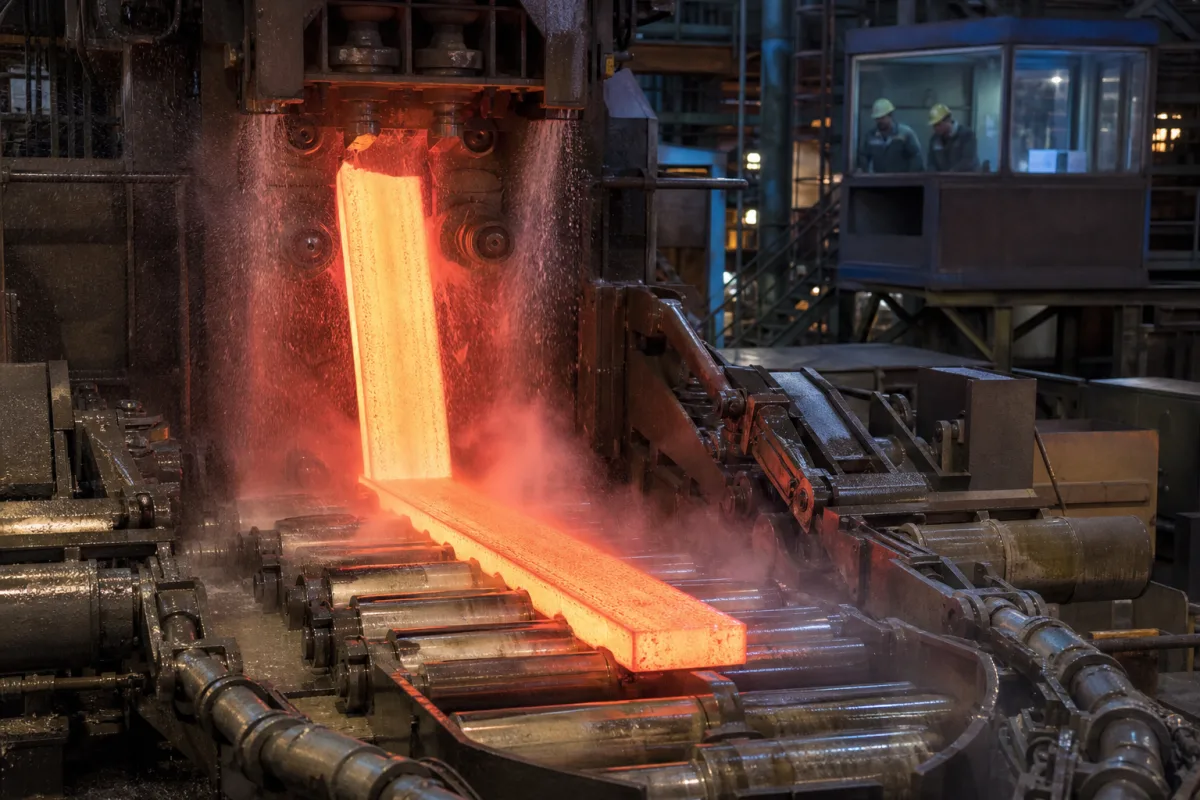
Automated extraction mechanism for intermittent continuous casting: the pull–pause–push-back withdrawal drive of horizontal and upward casters
Intermittent strand withdrawal for horizontal and upward continuous casting · pull, pause and push-back steps in a 0.5 s cycle, forward strokes of 1 to 1½ in against reverse strokes of 0.08 to 0.13 in, and servo drives pulling 8 mm oxygen-free copper rod
A horizontal or upward continuous caster has a short, cooled die fed directly from the furnace. The skin that forms in the die is thin, so the extraction mechanism moves the strand in a programmed pattern: a pull that draws new metal into the die, a pause that lets fresh skin form, and a short push back that presses the skin against the die and compensates for shrinkage. The withdrawal rolls or servo drive that produce this pattern, and the profile they follow, decide surface marks, internal porosity and how fast the line can run.
Withdrawal (extraction) mechanisms that move the strand intermittently through the die of horizontal and upward continuous casters: driven withdrawal and pinch rolls, servo drives, pull–pause–push-back motion profiles, and the slack loops that turn stepped motion into steady feed for downstream rolling. Complete non-ferrous casting machines are covered on the Continuous casting machine for non-ferrous metals page and their cut-off saws on the Cutting system for non-ferrous continuous casting page, and twin-roll and twin-belt strip casters on the Non-ferrous strip continuous casting and rolling line page; pinch-roll withdrawal and straightening of curved steel billet casters is covered on the Withdrawal and straightening unit page.
CNFX editorial research · Sources checked October 13, 2026 · 4 sources
Pull, pause, push back in half a second: why NKK slowed the first 2 mm of every pull
NKK's patent application EP0511410A1 sets out the conventional horizontal casting cycle for sections of 80 to 350 mm cast at not less than 1.6 m/min, then changes how each pull begins. [1]
NKK notes that the earlier fix was a mechanical seal of thin carbon sheet between mould, brake ring and feed tube, which needed accurate machining and careful refitting each time a brake ring was changed, more so on multi-strand machines; its alternative is a change in the drive's velocity profile only. [1]
Editorial calculation: 1.6 m/min at 120 cycles/min is a net advance of about 13.3 mm per cycle; the 2 mm low-acceleration phase is therefore roughly the first sixth of each net step.
0.2 s; the strand is pushed slightly back toward the mould [1]
Defect
Air drawn in at the triple point between mould and brake ring during the speed-up, leaving bubbles under the surface that become linear flaws after rolling [1]
NKK change
Initial acceleration cut to 0.4–0.6 m/s², about a quarter of the conventional value, over the first 2 mm of withdrawal, then increased [1]
Give the section size and casting speed, the cycle rate, the pull, pause and push-back times, and whether the drive can follow a curved acceleration profile at the start of each pull.
02
Forward 1 to 1½ in, back 0.08 to 0.13 in at 1 to 3 Hz: the stroke pattern for brass rod and a slack loop to steady it
Kennecott's EP0010707A1 explains why the strand moves in strokes at all: a cycle of forward and reverse strokes helps form the casting skin, prevents the casting from breaking off and compensates for contraction in the die. In its caster a driven withdrawal roll and a pinch roll draw the rod through a stationary chilled mould. [2]
A rolling mill needs steady feed, so Kennecott turns the rod through 70 to 110°, preferably 90°, over guide rolls on an arc, lets slack form by lateral deflection between grooved rolls near the middle of the arc, and uses a transducer on the slack to set the mill speed equal to the net casting speed times a reduction constant. In an alternative, the mould oscillates while the rod is withdrawn at steady speed. [2]
Editorial note: the reverse stroke is a few percent of the forward stroke but runs at higher acceleration, so the drive, rolls and rod grip have to reverse load one to three times a second without slipping; ask how roll slip is detected.
For example 1 to 1½ in, at 3 to 20 in/s and above 1 g [2]
25.4 to 38.1 mm; 76 to 508 mm/s
Reverse stroke
For example 0.08 to 0.13 in, at 3 g in the example given [2]
2.0 to 3.3 mm
Dwell
For example 0.1 s at the end of either or both strokes [2]
—
State the rod or strip size and alloy, net speed, stroke lengths and frequency, peak accelerations, and whether downstream equipment needs a slack loop or runs from the intermittent strand.
03
Servo-driven upward extraction of 8 mm oxygen-free copper rod, and the defects that follow the motion
In the UPCAST upward process the cooled dies are fixed to a frame above the casting furnace, one cooler per strand, and a servomotor-driven system pulls the rods or tubes upward through the coolers to the coilers. [3]
UPCAST describes 8 mm as the industry-standard rod diameter for wire and cable production. It states that its oxygen-free copper contains 1–3 ppm oxygen and is cast to final size without hot rolling, and that a product change means fitting other coolers and selecting the matching casting program in the computer-controlled servo drive. Multiple drive systems can be integrated into one frame, so different rod or tube sizes can be cast at the same time, and output is adjusted by the number of active strands. Single-furnace lines are offered for up to 12,000 t/year and double-furnace lines for up to 40,000 t/year. [3]
Jones and co-authors at the University of Dundee examined 8 mm oxygen-free copper rod with pulse marks on its surface and periodic centreline macroporosity of pores larger than 1 mm, defects that limited the attainable withdrawal rate but also appeared at slower rates. Using tensile tests, optical and CT imaging and CFD modelling of hotspots in the die, they linked the defects to the withdrawal, dwell and push-back motions and to the pitch length of the marks, and identified a porosity mechanism that does not depend on the average withdrawal rate. [4]
Editorial note: because the Dundee work ties defects to the shape of the motion rather than the average speed, a quotation for an extraction drive should state the motion profiles it can execute and how they are programmed, not only its maximum speed.
State the product (rod or tube), diameter and alloy, the number of strands, the target output per year and the motion profiles the servo drive must support.
04
What to send for an extraction mechanism
Paste it into your enquiry below or into an email to a maker, then replace every bracket.
Caster: [horizontal or upward; strands; die size]
Product: [alloy; rod, tube, strip or section size]
Motion: [pull, pause and push-back times or strokes; frequency; accelerations]
Speed: [net withdrawal speed; target output]
Drive: [servo or roll drive; profile programming]
Downstream: [coiler, saw or rolling mill; slack loop]
Explore company information and manufacturing capabilities, then discuss the scope of your project with a relevant supplier.
Share this page
Compiled and source-reviewed by the CNFX editorial team.
Each manufacturer above links to the page on that company's own website where the product is listed, with the date we checked it. How we source and review
· Page last updated 13 October 2026
Buyer questions
What is a pull–pause–push-back withdrawal cycle?
NKK's EP0511410A1 describes a conventional horizontal casting cycle of about 0.5 s at 120 cycles/min: a 0.2 s pull, a 0.1 s pause and a 0.2 s push back toward the mould. [1]
How long are the strokes when casting brass rod intermittently?
Kennecott's EP0010707A1 gives, for 3/4 in rod, forward strokes of 1 to 1½ in and reverse strokes of 0.08 to 0.13 in at about 1 to 3 Hz, with net speed above 80 in/min. [2]
What drives the strand in upward continuous casting of copper?
UPCAST uses a servomotor-driven system that pulls each strand upward through its own cooler, with casting programs selected per product. [3]
Sources and what still needs a direct check
Sources checked 2026-10-13. The horizontal cycle and acceleration change come from NKK's EP0511410A1; stroke lengths and the slack loop from Kennecott's EP0010707A1; servo upcasting from UPCAST's technology page; motion-related defects from Jones et al., Metallurgical and Materials Transactions B (2023).