Editorial Technical Reference

Charging/Discharging System

This page explains how Charging/Discharging System is classified within Basic Metal Manufacturing. Technical values and manufacturer relationships are research references; confirm the current specification and supplier evidence for each order.

Technical Definition & Core Assembly

Mechanical system for loading and unloading materials into and out of a reheating furnace
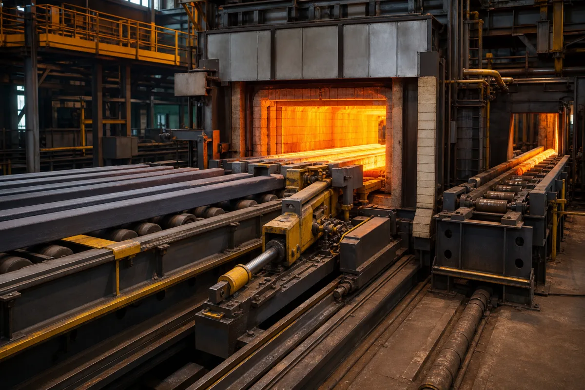
Representative product image. Confirm appearance and specifications with the manufacturer.

Product Specifications

Technical details and manufacturing context for Charging/Discharging System

Definition
The Charging/Discharging System is a specialized mechanical component integrated into reheating furnaces used in basic metal manufacturing. It handles the controlled insertion (charging) of cold or pre-heated materials into the furnace and the extraction (discharging) of heated materials from the furnace. The system ensures proper material flow, positioning, and timing to maintain furnace efficiency and product quality. It typically employs conveyors, pushers, extractors, or walking beams to move materials. During charging, it positions the material at the furnace entrance; the furnace's internal mechanism then moves it through heating zones. Upon completion of the heating cycle, the discharging mechanism retrieves the hot material from the furnace exit and transfers it to the next processing stage, such as rolling or forging. The system is designed for heavy-duty operation, with a rated load capacity of 5–20 tonnes per charge and an operating speed of 0.1–0.5 m/s. Positioning accuracy is ±5 mm to ensure correct placement. It operates in ambient temperatures from -20°C to 60°C and can handle materials up to 1200°C. Drive power ranges from 5.5 to 22 kW, with supply voltage of 380–480 V AC (three-phase, 50/60 Hz, per IEC 60038) and control voltage of 24 V DC. Ingress protection is IP54–IP65 per IEC 60529. Structural or stainless steel grades Q235B/304 are used, referencing GB/T 700 and GB/T 3280. Overall dimensions are customizable (3000–8000×1500–3000×1000–2000 mm), and total weight ranges from 3000 to 15000 kg. Materials on file include heat-resistant alloy steel, refractory materials, and ceramic components. These specifications are reference ranges; verify model-specific values and standards with the legal manufacturer or supplier.
Working Principle
The system uses a combination of conveyors, pushers, extractors, or walking beams to move materials. During charging, it positions the material at the furnace entrance. The furnace's internal mechanism then moves it through heating zones. Upon completion of the heating cycle, the discharging mechanism retrieves the hot material from the furnace exit and transfers it to the next processing stage, such as rolling or forging.
Common Materials
Heat-resistant alloy steel, Refractory materials, Ceramic components
Technical Parameters
ParameterTypical rangeNotes & selection driver
Rated Load Capacity5–20 tMaximum material weight per charge
Operating Speed0.1–0.5 m/sAffects cycle time and thermal uniformity
Positioning Accuracy±5 mmEnsures correct placement in furnace
Operating Temperature-20–60 °CAmbient temperature range
Max Material Temperature1200 °CFor handling hot materials
Drive Power5.5–22 kWDepends on load and speed
Supply Voltage380–480 V ACThree-phase, 50/60 HzIEC 60038
Control Voltage24 V DCFor PLC and sensors
Ingress ProtectionIP54–IP65Dust and water resistanceIEC 60529
Material GradeQ235B/304Structural or stainless steelGB/T 700, GB/T 3280
Overall Dimensions (L×W×H)3000–8000×1500–3000×1000–2000 mmCustomizable per furnace layout
Total Weight3000–15000 kgIncluding frame and drive

Ranges are indicative industry figures for RFQ preparation, not a supplier commitment. Confirm every value and standard with the legal manufacturer before ordering.

Components / BOM
  • Charging Table
    Receives and positions cold material before entry into the furnace
    Material: Steel with refractory lining
  • Pusher/Extractor Mechanism
    Mechanically pushes material into the furnace or extracts it from the furnace
    Material: Heat-resistant alloy steel
  • Discharge Table
    Receives and transfers hot material from the furnace to downstream equipment
    Material: Water-cooled steel or refractory material
  • Drive System
    Provides mechanical power for the movement of charging/discharging components
    Material: Steel, electric motors, gearboxes
  • Walking Beam Optional
    Lifts, advances and lowers the stock through the furnace in steps, on walking-beam furnaces.

Industry Taxonomies & Aliases

Commonly used trade names and technical identifiers for Charging/Discharging System.

Applied To / Applications

This component is essential for the following industrial systems and equipment:

Industrial Ecosystem & Supply Chain Structure

Complementary Systems
Downstream Applications
Specialized Tooling

Application Fit & Sizing Matrix

Operational Limits
pressure: Atmospheric to 2 bar (sealed systems)
flow rate: 1-50 tons/hour (material dependent)
max payload: Up to 5000 kg per cycle
temperature: Ambient to 1200°C (furnace interface dependent)
slurry concentration: Not applicable (solid materials only)
Media Compatibility
✓ Steel billets/slabs ✓ Aluminum ingots ✓ Ceramic components
Unsuitable: Molten metal or corrosive chemical environments
Sizing Data Required
  • Furnace chamber dimensions (LxWxH)
  • Material density and piece dimensions
  • Required throughput (tons/hour)

Reliability & Engineering Risk Analysis

Failure Mode & Root Cause
Overheating of battery cells
Cause: Excessive charging/discharging currents, poor thermal management, or internal short circuits leading to thermal runaway.
Corrosion of electrical connectors
Cause: Exposure to moisture, contaminants, or galvanic corrosion due to dissimilar metals in connectors and terminals.
Maintenance Indicators
  • Unusual hissing, popping, or crackling sounds from battery compartments indicating gas venting or arcing.
  • Visible swelling, leakage, or discoloration of battery cells or housing, suggesting internal failure or overheating.
Engineering Tips
  • Implement predictive maintenance using thermal imaging and impedance testing to detect early signs of cell degradation or connection issues.
  • Ensure proper environmental controls (e.g., temperature, humidity) and use corrosion-resistant materials for connectors to prevent electrochemical damage.

Indicative industry ranges for design and RFQ preparation. Confirm the exact figures and applicable standard with the manufacturer before specifying.

Compliance & Manufacturing Standards

Applicable Standards
ISO 15118 (Road vehicles - Vehicle to grid communication interface) ANSI/UL 2202 (Standard for Electric Vehicle (EV) Charging System Equipment) DIN EN 61851-1 (Electric vehicle conductive charging system - General requirements)

Quoted from the published standard.

Manufacturing Precision
  • Voltage regulation: +/- 2% of nominal output
  • Connector mating force: 50-150 N
Quality Inspection
  • Insulation resistance test (minimum 1 MΩ at 500 VDC)
  • Leakage current test (maximum 3.5 mA under normal conditions)

Manufacturers of Charging/Discharging System

Manufacturer profiles associated with Charging/Discharging System.

Sourcing Charging/Discharging System from China?
Tell us your specification and target quantity — we will match it against manufacturer records and come back with the factories that fit.
Request manufacturers We manufacture this

Manufacturer listings support early research and capability understanding. They are not certification, ranking, or transaction guarantees.

Technical documentation
Request current drawings, revision history, and a signed specification sheet.
Manufacturing capability
Verify equipment lists, process limits, capacity, and representative production evidence.
Inspection readiness
Confirm test methods, calibrated equipment, sampling plans, and traceable reports.
Supplier transparency
Check the legal entity, factory address, ownership, certifications, and direct contacts.

CNFX does not score or rank suppliers. Buyers must verify all claims and documents with the legal manufacturer before ordering.

Supply Chain Compatible Machinery & Devices

Continuous Casting Machine

Industrial machine for solidifying molten metal into continuous billets/blooms/slabs.

Explore Specs →
Vacuum Induction Melting Furnace

Industrial furnace for melting metals under vacuum using electromagnetic induction

Explore Specs →
Electroslag Remelting Furnace

An industrial furnace used in basic metal manufacturing for secondary refining of alloys through the electroslag remelting (ESR) process.

Explore Specs →
Molten Metal Temperature Measurement System

Automated system for continuous temperature monitoring of molten metals during processing.

Explore Specs →

Frequently Asked Questions

What is the typical load capacity of this charging/discharging system?

The rated load capacity is 5–20 tonnes per charge, as listed in the reference parameters. However, the exact capacity depends on the specific model and furnace layout, so you should confirm with the manufacturer or supplier.

What materials are used in the construction of the system?

The system may use heat-resistant alloy steel, refractory materials, and ceramic components. Structural or stainless steel grades Q235B or 304 are referenced, but the actual material grade should be verified with the supplier for your application.

What is the positioning accuracy of the system?

The positioning accuracy is ±5 mm, which ensures correct placement of materials in the furnace. This value is a reference and may vary with the specific model and installation.

What standards apply to the electrical and protection aspects?

The supply voltage references IEC 60038, and ingress protection references IEC 60529 (IP54–IP65). These are procurement references; compliance should be confirmed with the manufacturer.

Data Basis

Editorial classification, named public sources where available, and source-reviewed manufacturer records.

Preliminary Technical Classification
This page supports structured research, RFQ preparation, and supplier evaluation. It does not replace buyer-led supplier qualification, standards review, or technical approval.
Buyer enquiry

Request manufacturing insight for Charging/Discharging System

Ask for use case, specification boundaries, supplier type, and RFQ preparation information for this product.

Where it goes
Straight to the CNFX editorial desk, and to the manufacturer if this product is linked to a claimed profile. Nothing is broadcast to a supplier list.
Your details stay here
We do not sell or rent enquiry data, and we do not add you to a mailing list. Used only to answer this request.
No commission, no middleman
CNFX is a directory. We take no cut of any order and never negotiate on a supplier's behalf.
What we don't claim
A listing is not an endorsement. Qualify every supplier and verify every figure yourself before ordering.

Your business information is used only to process this request.

Thank you! Your message has been sent. We'll respond within 1–3 business days.
Sorry, we couldn't send your message. Please try again, or email us at contact@cnfx.com.

Need to Manufacture Charging/Discharging System?

Compare manufacturer profiles with relevant product and process capability.

Previous Product
Work Rolls
Last Product
Get QuotesChat