Editorial Technical Reference

Coil Ejection System

This page explains how Coil Ejection System is classified within Basic Metal Manufacturing. Technical values and manufacturer relationships are research references; confirm the current specification and supplier evidence for each order.

Technical Definition & Core Assembly

A mechanical system within a downcoiler that safely removes finished steel coils from the mandrel and transfers them to the next processing stage.
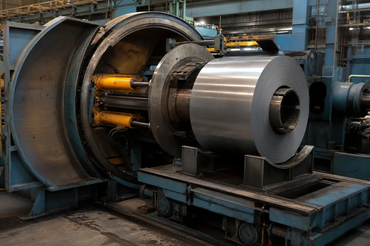
Representative product image. Confirm appearance and specifications with the manufacturer.

Product Specifications

Technical details and manufacturing context for Coil Ejection System

Definition
The coil ejection system is a critical component of a downcoiler in steel manufacturing. It operates after the steel strip has been wound into a tight coil on the mandrel. The system's primary function is to disengage the completed coil from the mandrel, lift it, and transfer it to a conveyor, cooling bed, or packing station, ensuring efficient material flow and preventing damage to the coil surface. The system is designed for basic metal manufacturing environments, typically handling coils with outer diameters from 800 to 2000 mm, widths from 600 to 1600 mm, and weights from 5 to 30 metric tons. It features an ejection stroke of 300 to 600 mm, an ejection speed of 0.1 to 0.3 m/s, and a positioning accuracy of ±1.0 mm. The system operates within a temperature range of -10 to 60 °C and has an ingress protection rating of IP54 to IP65. Hydraulic actuation requires an oil flow rate of 40 to 80 L/min and an operating pressure of 1.0 to 1.6 MPa, with the note that The cycle time for one complete ejection is 15 to 30 seconds. The system is constructed from high-strength steel and structural steel grade Q235B per GB/T 700, with a total weight of 3000 to 5000 kg and overall dimensions of 2500×1500×1200 mm. These values are reference ranges and must be verified for the specific model and application. The system is a component, not a standalone machine, and its integration with the downcoiler and downstream equipment must be confirmed with the manufacturer or supplier.
Working Principle
The system typically uses hydraulic or electromechanical actuators. After coil formation, the mandrel collapses or retracts. Ejector arms or plates then engage the coil's inner diameter or bottom surface. These arms lift and push the coil axially off the mandrel onto a waiting transfer car, chain conveyor, or tilting cradle. The motion is precisely controlled to maintain coil integrity. The ejection stroke and speed are adjustable within the specified ranges to suit different coil sizes and process requirements. The system's control logic ensures that the coil is released only after the mandrel is fully retracted, preventing damage. The positioning accuracy ensures that the coil is placed accurately on the exit conveyor for further processing.
Common Materials
High-strength steel
Technical Parameters
ParameterTypical rangeNotes & selection driver
Coil Weight Capacity5–30 tMaximum coil weight the system can handle
Coil Outer Diameter800–2000 mmRange of coil outer diameters accommodated
Coil Width600–1600 mmRange of coil widths accommodated
Ejection Stroke300–600 mmDistance the coil is pushed off the mandrel
Ejection Speed0.1–0.3 m/sSpeed of the ejection arm
Operating Pressure1.0–1.6 MPa
Hydraulic Oil Flow Rate40–80 L/minRequired flow for hydraulic actuation
Positioning Accuracy±1.0 mmAccuracy of coil placement on the exit conveyor
Cycle Time15–30 sTime for one complete ejection cycle
Operating Temperature-10–60 °CAmbient temperature range for reliable operation
Ingress Protection RatingIP54–IP65Protection against dust and water jetsIEC 60529
Material GradeQ235BStructural steel for frame and componentsGB/T 700
Weight3000–5000 kgTotal weight of the ejection system
Footprint (L×W×H)2500×1500×1200 mmOverall dimensions of the system

Ranges are indicative industry figures for RFQ preparation, not a supplier commitment. Confirm every value and standard with the legal manufacturer before ordering.

Components / BOM
  • Ejector Arm/Plate Part
    The primary contact surface that pushes against the coil's inner diameter or face to provide the ejection force.
    Material: Hardened steel
  • Hydraulic Cylinder / Linear Actuator
    Provides the controlled linear force and motion to drive the ejector arm.
    Material: Steel (cylinder body), Chrome-plated steel (piston rod)
  • Guide Rails/Bearings Part
    Ensures smooth, aligned linear motion of the ejector mechanism during operation.
    Material: Steel with bronze or polymer bushings
  • Control Logic Unit
    Interlocks ejection against mandrel retraction, and holds the stroke and speed settings.

Applied To / Applications

This component is essential for the following industrial systems and equipment:

Industrial Ecosystem & Supply Chain Structure

Complementary Systems
Downstream Applications
Specialized Tooling

Application Fit & Sizing Matrix

Operational Limits
pressure: Hydraulic system: 150-250 bar (2175-3625 psi), Pneumatic system: 6-10 bar (87-145 psi)
other spec: Coil weight capacity: 5-45 metric tons, Coil diameter range: 800-2100 mm, Coil width range: 600-2000 mm, Cycle time: 30-90 seconds per coil
temperature: Ambient to 150°C (302°F) - typical steel mill environment
Media Compatibility
✓ Hot-rolled steel coils ✓ Cold-rolled steel coils ✓ Galvanized steel coils
Unsuitable: Continuous casting environments with molten metal exposure
Sizing Data Required
  • Maximum coil weight (metric tons)
  • Coil outer diameter range (mm)
  • Required cycle time (seconds per coil)

Reliability & Engineering Risk Analysis

Failure Mode & Root Cause
Misalignment-induced wear
Cause: Improper installation or thermal expansion causing guide rails, rollers, or actuators to deviate from specified alignment, leading to uneven force distribution, increased friction, and accelerated component degradation.
Hydraulic/pneumatic system failure
Cause: Contamination (e.g., particulate ingress, moisture) in fluid lines or air supply, resulting in valve sticking, cylinder seal degradation, pressure loss, or erratic ejection force and timing.
Maintenance Indicators
  • Audible grinding, scraping, or irregular knocking during coil ejection cycles
  • Visible misalignment or wobble of ejected coils, or inconsistent ejection distances
Engineering Tips
  • Implement laser alignment checks and thermal growth compensation during installation, and schedule regular alignment verification using precision tools to maintain optimal component positioning.
  • Install high-efficiency filtration (e.g., 5-micron filters for hydraulic systems, coalescing filters for pneumatic systems) and enforce strict fluid/air quality monitoring protocols to prevent contamination-related failures.

Indicative industry ranges for design and RFQ preparation. Confirm the exact figures and applicable standard with the manufacturer before specifying.

Compliance & Manufacturing Standards

Applicable Standards
ISO 12100:2010 - Safety of machinery CE Marking - Machinery Directive 2006/42/EC

Quoted from the published standard.

Manufacturing Precision
  • Shaft alignment: +/-0.05mm
  • Coil positioning repeatability: +/-0.1mm
Quality Inspection
  • Functional safety test - Emergency stop verification
  • Dimensional accuracy check - Laser alignment measurement

Manufacturers of Coil Ejection System

Manufacturer profiles associated with Coil Ejection System.

Sourcing Coil Ejection System from China?
Tell us your specification and target quantity — we will match it against manufacturer records and come back with the factories that fit.
Request manufacturers We manufacture this

Manufacturer listings support early research and capability understanding. They are not certification, ranking, or transaction guarantees.

Technical documentation
Request current drawings, revision history, and a signed specification sheet.
Manufacturing capability
Verify equipment lists, process limits, capacity, and representative production evidence.
Inspection readiness
Confirm test methods, calibrated equipment, sampling plans, and traceable reports.
Supplier transparency
Check the legal entity, factory address, ownership, certifications, and direct contacts.

CNFX does not score or rank suppliers. Buyers must verify all claims and documents with the legal manufacturer before ordering.

Supply Chain Compatible Machinery & Devices

Vacuum Induction Melting Furnace

Industrial furnace for melting metals under vacuum using electromagnetic induction

Explore Specs →
Electroslag Remelting Furnace

An industrial furnace used in basic metal manufacturing for secondary refining of alloys through the electroslag remelting (ESR) process.

Explore Specs →
Molten Metal Temperature Measurement System

Automated system for continuous temperature monitoring of molten metals during processing.

Explore Specs →
Molten Metal Degassing System

The Molten Metal Degassing System is an industrial system used in basic metal manufacturing to remove dissolved hydrogen, oxygen, and nitrogen from molten aluminum, steel, and other non-ferrous metals.

Explore Specs →

Frequently Asked Questions

What is the function of a coil ejection system?

It removes finished steel coils from the downcoiler mandrel and transfers them to the next stage, such as a conveyor or packing station, ensuring safe and efficient material flow.

What are the typical capacity ranges for this system?

Reference ranges include coil weights of 5-30 metric tons, outer diameters of 800-2000 mm, and widths of 600-1600 mm. Actual capabilities depend on the specific model and must be confirmed with the supplier.

How is the coil ejected from the mandrel?

After the mandrel collapses or retracts, ejector arms or plates engage the coil and push it axially off the mandrel onto a transfer car or conveyor. The motion is hydraulically or electromechanically actuated and precisely controlled.

What standards apply to this system?

The system references standards such as IEC 60529 for ingress protection, and GB/T 700 for material grade. These are verification references; compliance must be confirmed with the manufacturer.

Data Basis

Editorial classification, named public sources where available, and source-reviewed manufacturer records.

Preliminary Technical Classification
This page supports structured research, RFQ preparation, and supplier evaluation. It does not replace buyer-led supplier qualification, standards review, or technical approval.
Buyer enquiry

Request manufacturing insight for Coil Ejection System

Ask for use case, specification boundaries, supplier type, and RFQ preparation information for this product.

Where it goes
Straight to the CNFX editorial desk, and to the manufacturer if this product is linked to a claimed profile. Nothing is broadcast to a supplier list.
Your details stay here
We do not sell or rent enquiry data, and we do not add you to a mailing list. Used only to answer this request.
No commission, no middleman
CNFX is a directory. We take no cut of any order and never negotiate on a supplier's behalf.
What we don't claim
A listing is not an endorsement. Qualify every supplier and verify every figure yourself before ordering.

Your business information is used only to process this request.

Thank you! Your message has been sent. We'll respond within 1–3 business days.
Sorry, we couldn't send your message. Please try again, or email us at contact@cnfx.com.

Need to Manufacture Coil Ejection System?

Compare manufacturer profiles with relevant product and process capability.

Previous Product
Work Rolls
Last Product
Get QuotesChat