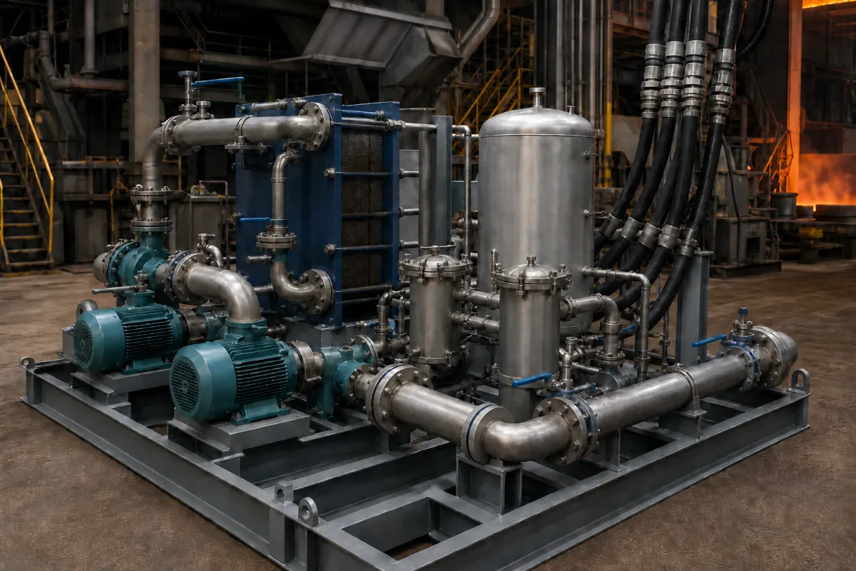
Oxygen lance cooling water system: closed-loop skid for steelmaking lances
Oxygen lance cooling water skids · inlet water temperature, inlet–outlet ΔT as a skull and leak signal, supply–return flow comparison, water quality
An oxygen lance cooling water system is the pumped, closed water circuit that carries cooling water down the jacket of a water-cooled oxygen lance to its copper tip and back, through a heat exchanger, strainers, a header tank and instrumentation mounted on a skid beside the converter. It does not make steel; it keeps the lance from burning through and tells the operator when something is wrong. Ask three things first: what flow, pressure and inlet temperature the lance maker requires, how the system will detect a water leak, and what water quality the circuit will run on.
Closed-loop pump, heat-exchanger and monitoring skids that cool water-cooled oxygen lances in top-blown converters, specified by inlet temperature, temperature rise, supply and return flow monitoring and water quality. Converter vessels, trunnion rings, hoods and their emission control are covered on the Basic oxygen furnace vessel page. The lance body and nozzle as a purchased part, blast furnace stave and tuyere cooling plants, and plant-wide cooling towers are outside this page except where their practice is compared.
CNFX editorial research · Sources checked October 12, 2026 · 5 sources
Use the inlet–outlet temperature rise to watch the lance
In a heat-transfer study by Havelia, Malathi and Deo (IIT Kanpur, 2004), the oxygen lance of a top-blown converter is three concentric steel pipes, and water at 22–25 °C is circulated through it at high pressure to keep the outermost surface of the lance within 150 °C. The authors state that the temperature difference between inlet and exit cooling water is a direct measure of the condition of the lance. [1]
Their model of a lance for a 100 t vessel used an outer tube 0.159 m in outside diameter with a 4.5 mm wall, and found that radiation from the hot spots where the oxygen jets strike the bath supplied approximately 90–95% of the heat received by the lance. When metal skull builds up on the lance, heat transfer to the water and the temperature rise both increase; the authors suggest that, once the expected rise is known for each lance position, a rise above it can prompt the blower to lower the lance briefly to melt the skull. [1]
At the tip, flow distribution matters as much as total flow. A FLUENT study at Northeastern University (Shenyang) found dead zones in the cooling water passages of a conventional copper lance tip; adding streamlined guide ribs created a swirling flow and lowered the average end-face temperature by 10 °C in the simulation. [2] Berry Metal's lance patent notes temperature peaks of up to 3000 °C at the front of the lance head and recommends flushing the head "with a large volume of cool water under high pressure". [3]
Editorial note: the skid supplier cannot pick these numbers for you. The flow, inlet pressure, maximum inlet temperature and allowed temperature rise come from the lance and tip designer; the skid has to deliver them at the far end of the hoses and measure them reliably.
Give the supplier the lance maker's required flow, inlet pressure at the lance, maximum inlet temperature and design temperature rise, the number of lances and whether a standby lance is cooled, hose and pipe run lengths and elevation, heat load, available plant water or air for the heat exchanger, and the alarm and trip signals the converter control needs.
02
Plan how the circuit will detect a water leak
Hokushin Electric Works' patent on cooling-conduit monitoring explains the principle used in iron-making: a flowmeter in the inlet line and another in the outlet line of each cooled element, with an alarm when the difference between them exceeds a set level, because water leaking into the furnace degrades product quality and heavy leakage brings a danger of explosion. A blast furnace with 20 to 40 tuyeres needs 40 to 80 flowmeters for this. [4]
The same patent warns that contaminants such as rubbish or thread sticking unevenly to the probes of vortex meters create false flow differences that cannot be told apart from a leak. [4] KROHNE describes a blast furnace leak-monitoring system at a Ukrainian works that uses more than 530 electromagnetic flowmeters in DN 32 to DN 80 on closed-loop cooling circuits, measuring the difference between supply and return and raising an alarm when it exceeds a limit; the chemically purified water there has a conductivity of 1400–1600 µS/cm, runs at 6–12 barg and 40–60 °C, and reaches 104 °C in some places. [5]
Editorial note: a lance is one cooled element rather than dozens, but the same logic applies, since the water sits close to molten metal. Ask the supplier which flowmeter principle is used on the supply and return lines, how the difference alarm is set and filtered against false trips, and what the converter control does on a low-flow, high-ΔT or flow-difference signal.
03
Pumps, exchanger, strainers and the two meters a lance skid carries
The flowmeters and temperature sensors are the parts that turn the skid from a pump set into a lance protection system.
Component
Role
Fix in the order
Circulating pumps (duty and standby)
Deliver the flow and pressure the lance needs.
Flow, head at the lance, standby arrangement.
Heat exchanger
Removes lance heat to plant water or air.
Heat load, approach temperature, materials.
Header or expansion tank
Holds the closed-loop volume.
Volume, make-up and venting.
Strainers or filters
Keep debris out of tip passages and meter probes. [4]
Inlet–outlet difference used to track lance condition. [1]
Design ΔT and monitoring logic.
Pressure Drop (MPa)
Loss across hoses, lance and tip.
Value at rated flow.
Water Quality
One closed loop ran chemically purified water at 1400–1600 µS/cm. [5]
Treatment, conductivity, filtration.
Material
Pipes, exchanger plates, tank.
Material for each part.
Power Consumption (kW)
Pumps and fans.
Installed and running power.
Dimensions (L×W×H) (mm)
Skid footprint.
General arrangement drawing.
Weight (kg)
Skid dry and operating weight.
Both weights.
05
Send the lance, water and monitoring data together
Paste it into your enquiry below or into an email to a maker, then replace every bracket.
Lance: [maker; number of lances; standby lance cooled or not]
Water duty: [flow; inlet pressure at lance; maximum inlet temperature; design ΔT; heat load]
Site: [hose and pipe lengths; elevation; plant water or air for heat rejection]
Water quality: [treatment; conductivity; filtration]
Monitoring: [supply and return flowmeters; temperature sensors; alarm and trip signals]
Skid: [pumps duty and standby; tank; materials; power]
Documents: [P&ID; GA drawing; instrument list]
The linked heat exchanger maker supplies one component of a lance cooling skid, not the full circuit.
Guangdong Jiema Energy Saving Technology Co.,Ltd
Manufacturing site to be confirmed for the order
Lists plate and shell-and-tube heat exchangers, including "Water coolers for cooling water in system"; a heat exchanger component, not a complete lance cooling skid.
Explore company information and manufacturing capabilities, then discuss the scope of your project with a relevant supplier.
Share this page
Compiled and source-reviewed by the CNFX editorial team.
Each manufacturer above links to the page on that company's own website where the product is listed, with the date we checked it. How we source and review
· Page last updated 13 October 2026
Buyer questions
Why is the inlet–outlet temperature difference watched on an oxygen lance?
The IIT Kanpur study calls it a direct measure of the lance's condition: skull build-up and lance position change the heat reaching the water, so ΔT rises above its expected value. [1]
How is a cooling water leak detected?
By comparing flow in the supply and return lines of a cooled element and alarming when the difference exceeds a set limit, as Hokushin's patent and KROHNE's blast furnace report describe. [4][5]
Why does the tip design matter for cooling?
A Northeastern University simulation found dead zones in a conventional tip's water passages; guide ribs lowered the average end-face temperature by 10 °C. [2]
Sources and what still needs a direct check
Sources checked 2026-10-12. The lance figures come from a university heat-transfer study and a university simulation; leak-detection practice comes from an instrument maker's application report and a patent, both written for blast furnaces. A lance maker's patent describes tip conditions. Your lance designer's data governs the final values.