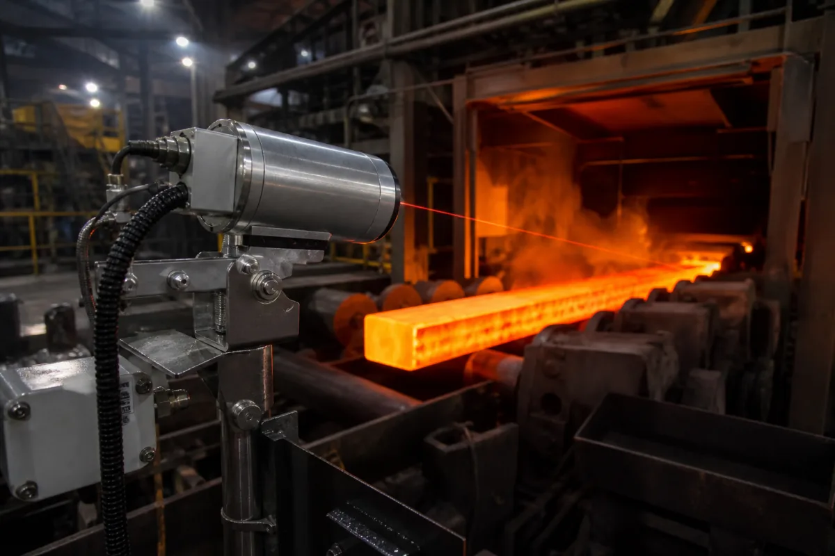
Infrared pyrometer for hot metal and furnace processes
Non-contact temperature in metals processing · Emissivity and wavelength, one-colour vs ratio pyrometers, attenuation and E-slope, spot size and D:S
An infrared pyrometer measures the temperature of a surface without contact by detecting the infrared radiation it emits; in steel and metal processing it is mounted on billets, strip, ladles and furnaces where contact sensors cannot follow. Ask three things first: which wavelength suits the material and temperature and how much an emissivity error will shift the reading, whether a one-colour or a ratio (two-colour) pyrometer is needed because of smoke, steam, dirty windows, small targets or changing surfaces, and whether the optics give a spot smaller than the target at the mounting distance.
Fixed and portable spot pyrometers (one-colour, ratio/two-colour and fibre-optic) for metals processing and high-temperature industry. Thermal imaging cameras, thermocouples and contact probes, and furnace control systems are outside this page.
CNFX editorial research · Sources checked October 12, 2026 · 4 sources
Fluke Process Instruments defines emissivity as a surface's ability to emit infrared energy, from 0 (shiny mirror) to 1.0 (blackbody), noting that "Most organic, painted, or oxidized surfaces have emissivity values close to 0.95." Its metals table gives steel at 0.35 polished and 0.8–0.9 oxidised or cold-rolled at 1.0 µm, molten steel 0.35 at 1.0 µm and 0.25–0.4 at 1.6 µm, and marks polished aluminium, polished brass, polished copper, chromium, gold and polished zinc as not recommended at 8–14 µm. It advises finding the emissivity for the instrument's spectral range, shielding the target from reflections of hotter surroundings, and using shorter-wavelength instruments for hotter objects where possible. [1]
Micro-Epsilon's infrared basics give Wien's displacement law, λmax · T = 2,898 µm·K, and the radiation constant c₂ = 1.44 × 10⁻² K·m, and show reading error for a 10% emissivity error falling as wavelength shortens from 8–14 µm to 1.1 µm. It recommends window materials by wavelength, such as Al₂O₃ for 1–4 µm up to 1,800 °C. [3]
Editorial calculation: a billet at 1,200 °C (1,473 K) peaks at 2,898 / 1,473 ≈ 2.0 µm. Using the Wien approximation, a 10% emissivity error shifts the reading by about λ T² / c₂ × 0.1: roughly 15 K at 1 µm, 24 K at 1.6 µm, but about 150 K at 10 µm. [3] This is why short-wavelength pyrometers are preferred on hot metal with uncertain emissivity.
Give the supplier the material and surface state (oxidised, scaled, bright, molten), temperature range, target size and mounting distance, line-of-sight conditions (smoke, steam, dust, windows), required response time and accuracy, ambient temperature at the sensor and cooling or purge available, output signal, and mounting and sighting needs.
02
Decide between one-colour and ratio pyrometers
Fluke Process Instruments lists cases where a one-colour pyrometer reads incorrectly: targets too small to fill the field of view, dust, smoke or steam in the line of sight, dirty process windows, and emissivity that changes with alloy or surface. A ratio (two-colour) pyrometer uses two detectors at two wavelengths seeing the same target and calibrates temperature from the ratio of their signals. [2]
In Fluke's example, a 1,500 °C blackbody gives 500 and 1,000 units at the two wavelengths, a ratio of 2; with 90% signal loss both fall to 50 and 100 units and the ratio and reading are unchanged. It states each two-colour instrument has an attenuation limit that can be as high as 95%. Because some targets such as molten metal have different emissivity at the two wavelengths, ratio pyrometers have an E-slope adjustment, set against a reference such as a disposable thermocouple. [2]
Micro-Epsilon defines the optics by the D:S ratio, measuring distance to spot diameter, and states a measurement is correct only if the object is larger than the spot; a target filling only part of the spot is read as an average with the cooler background. [3] Editorial calculation: at a D:S of 100:1 and 2 m distance the spot is 20 mm, so a one-colour pyrometer needs a target wider than that, while a ratio pyrometer can tolerate partial fill within its attenuation limit.
03
Match wavelength to the temperature range: one maker's model table
AMETEK Land's SPOT+ pyrometer page tabulates how wavelength tracks measuring range across one family. Single-wavelength (mono) models run from the 1.0 µm M100 at 500–1,800 °C (extendable to 2,500 °C) and the 1.6 µm M160 at 250–1,600 °C, through the 2.3 µm M210 at 50–1,100 °C and the 3.9 µm M390 at 150–1,800 °C, to the 3–5 µm M3-5 at 0–500 °C. Two-wavelength (ratio and mono) models are the R100 at 1.0 and 1.2 µm for 400–1,800 °C (extendable to 3,500 °C), the R160 at 1.0 and 1.5 µm for 250–1,600 °C, and the R210 at 2.1 and 2.4 µm for 125–1,100 °C; fibre-optic versions of the M100, M160, R100 and R160 keep the same ranges. Application models cover aluminium (200–900 °C), galvanneal strip (200–1,000 °C), molten metal (600–1,800 °C) and tube metal (300–1,800 °C). The page lists EtherNet/IP, Profinet, Modbus TCP and REST API connectivity, and purge air quality class 3 for particles, water and oil. [4]
Editorial calculation: by Wien's law (above), 1.0 µm is the peak for a body near 2,900 K, so short wavelengths sit on the steep side of the curve for hot metal and give smaller errors from emissivity changes, while the 3–5 µm band suits targets below 500 °C. For hot steel with dust or steam, a 1.0/1.2 µm ratio model matches the two-colour case described above; ask the supplier for the wavelength, D:S and response time of the exact model quoted. [4][3][2]
Two-colour, fibre-optic and wide-range pyrometers for metal processing
Listings include two-colour, fibre-optic and wide-range pyrometers for metal processing and general-purpose fixed pyrometers sold with process instruments; ask each for spectral range, D:S, attenuation limit for ratio models, response time and calibration certificate.
05
Optics and window, detectors, signal processing, sighting, and housing with cooling and purge
The detector row separates the two types: a one-colour unit reads one wavelength and needs the emissivity set, while a ratio unit uses two detectors on the same target and an E-slope setting for unequal spectral emissivity. [2]
Temperature range, emissivity, D:S, spectral band, accuracy and output for a pyrometer order
Match the spectral row to the range: AMETEK Land pairs 1.0 µm with 500–1,800 °C and 3–5 µm with 0–500 °C in one model family, and a shorter wavelength cuts the reading error from an emissivity error on hot metal. [4][3]
Field
What it means and published values
Ask the supplier for
Temperature range (°C)
Process span; e.g. 0–500 °C (3–5 µm) to 500–1,800 °C (1.0 µm). [4]
Range.
Emissivity setting (ratio)
Steel 0.35 polished, 0.8–0.9 oxidised at 1 µm. [1]
2 companies list this product among what they make. Company figures are quoted from each
company's own website; every card states where the relationship came from.
Dikai Optoelectronics
Manufacturing site to be confirmed for the order
Lists two-colour, fibre-optic, wide-range and handheld infrared pyrometers.
Explore company information and manufacturing capabilities, then discuss the scope of your project with a relevant supplier.
Share this page
Compiled and source-reviewed by the CNFX editorial team.
Each manufacturer above links to the page on that company's own website where the product is listed, with the date we checked it. How we source and review
· Page last updated 13 October 2026
Buyer questions
Why use a short-wavelength pyrometer on hot steel?
Fluke advises shorter wavelengths for hotter objects; by the Wien approximation a 10% emissivity error at 1,200 °C shifts a 1 µm reading by about 15 K but a 10 µm reading by about 150 K (editorial calculation). [1][3]
When do I need a ratio (two-colour) pyrometer?
Fluke lists small targets, smoke, steam, dust, dirty windows and changing emissivity; a ratio pyrometer keeps reading through signal loss up to its attenuation limit, which Fluke says varies by instrument and can be as high as 95%. [2]
What does D:S mean on a pyrometer?
Micro-Epsilon defines it as measuring distance divided by spot diameter; the target must be larger than the spot. [3]
Which wavelength should an infrared pyrometer use for hot metal?
One maker's range pairs 1.0 µm with 500–1,800 °C and 3–5 µm with 0–500 °C; its ratio models at 1.0/1.2 µm cover 400–1,800 °C. [4]
Sources and what still needs a direct check
Sources checked 2026-10-12. Fluke Process Instruments and Micro-Epsilon are pyrometer makers explaining measurement principles, and AMETEK Land publishes the wavelength and range table for its SPOT+ family; emissivity values are guides that vary with surface.