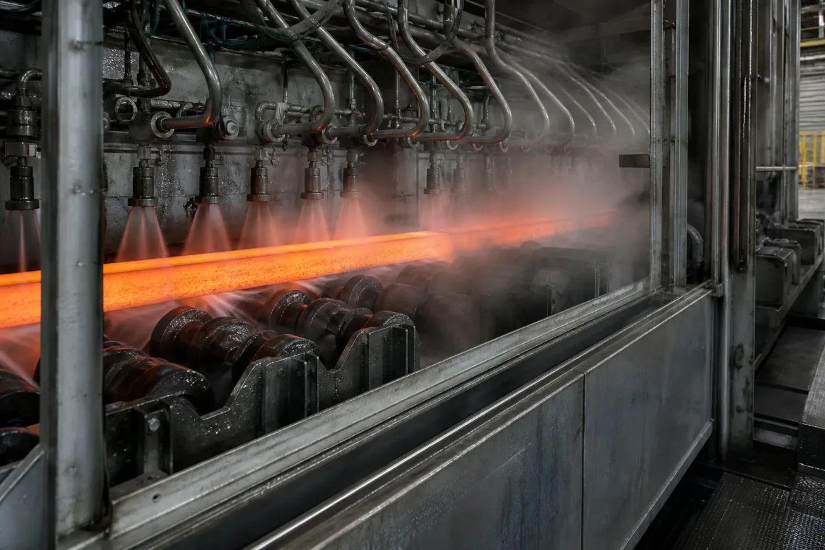
Secondary cooling chamber of a horizontal continuous caster: spray or contact cooling after the die for copper-alloy and cast-iron bars
Cooling beyond the die on horizontal continuous casters · copper-alloy bars that are already solid when they meet the spray, cast-iron profiles where the shell can remelt at the die exit, and a water-cooled graphite-lined shoe tried in place of water-air sprays
In a horizontal caster the die is fed from the side of a holding furnace and the strand is pulled out level, so gravity and the melt's pressure act on the top of a thin, hot shell as it leaves the die. What happens next depends on the metal and the section. A small copper-alloy bar can be solid well inside the die, so the secondary zone only takes heat out of solid metal; a large cast-iron profile can leave the die with a shell weak enough to remelt or break out. This page covers the cooling installed after the die for those two cases.
Secondary cooling after the die on horizontal continuous casters for copper-alloy and cast-iron bars and profiles: water sprays, water-air cooling, splash zones and contact shoes on the strand surface, and the chamber that holds them. Spray zones of vertical-bending and curved billet, bloom and slab casters are covered on the Secondary cooling (spray) zone of a continuous caster page and their chamber structure and foot rollers on the Secondary-cooling spray chamber structure page; the complete steel caster is covered on the Billet continuous caster page.
CNFX editorial research · Sources checked October 13, 2026 · 3 sources
Copper-alloy bars already solid at the spray: 16 or 36 L/min of secondary water moves the liquid core by under 1 mm
Hua and Li modelled horizontal continuous casting of Cu-0.8Cr alloy bars of 14, 21 and 28 mm diameter in ProCAST, with a 320 mm graphite die inside a 160 mm water-cooled copper sleeve, and secondary water sprayed through a circular nozzle onto the bar after it. [1]
Editorial calculation: even the longest liquid core, 32.42 mm, is about a tenth of the 320 mm graphite die, so in this model every bar is solid before it reaches the secondary water; that is consistent with the study's finding that secondary flow had the weakest effect of the four parameters. [1]
The authors also warn that higher casting speed raises shell temperature at the die exit and lowers its fracture strength, so that friction between die and shell can open surface cracks. [1] Editorial note: for small copper-alloy bars the secondary chamber is sized for the bar temperature at the coiler, saw or downstream process rather than for solidification.
Model input or result
Value in the Cu-0.8Cr study
Levels tested
Casting 1180 or 1280 °C; speed 600 or 1400 mm/min; primary and secondary water 16 or 36 L/min [1]
Liquid core length
16.68–20.93 mm (Ø14), 17.91–24.35 mm (Ø21), 20.90–32.42 mm (Ø28), measured from the melt level in the die [1]
Effect of secondary water
Main effect −0.02 mm (Ø14), 0.03 mm (Ø21), 0.74 mm (Ø28) [1]
Effect of casting speed
Main effect 2.59, 3.79 and 7.01 mm for the three diameters [1]
Splash zone between primary and secondary cooling
Heat transfer coefficient set to 5000 W/(m²·K) [1]
Recommended setting
1180 °C, primary 36 L/min, secondary 16 L/min; 1400 mm/min for Ø14 and Ø21, 600 mm/min for Ø28 [1]
Give the alloy, bar diameter or section, casting speed, die length, the temperature wanted at the end of the chamber and the water flow and quality available.
02
Cast-iron profiles: hot inner corners at 1020–1030 °C and a water-cooled graphite shoe in place of water-air sprays
Demchenko and Marukovich (Belarusian National Technical University and the Association of Foundrymen and Metallurgists of Belarus) describe shell remelting and breakout at the die exit as a cause of unstable horizontal continuous casting of iron, driven by convection in the liquid pool and the metallostatic pressure of the melt in the receiver; breakouts occur in the upper part of the casting, more so on large profiles taller than they are wide. [2]
The shoe sits on the top surface right against the end of the die, cooling the shell where it reheats and holding it against bulging with its own mass; the authors prefer the graphite-lined version because graphite is easily machined to round or trapezoidal sections and the liner is simple to replace when worn. [2]
Editorial calculation: 0.36 m/min against 0.28 m/min is about 29 % faster at the 20 °C lower iron temperature in the receiver.
Industrial trial on a cast-iron machine-table billet
Published value
Iron temperature in the receiver and mean withdrawal speed
Inner corners of the top surface, at 1020–1030 °C, close to the iron's solidification temperature [2]
Shoe length
Working surface at least 2.0–2.5 times the length of the reheating zone [2]
Shoe designs
Water-cooled metal casing with a replaceable graphite liner shaped to the top surface; or two sprung water-cooled metal sections [2]
Result
Surface temperature at vulnerable points lowered by 20–70 °C; mean casting speed raised 5–8 % for some billet sizes; breakouts almost eliminated; conventional secondary cooling no longer needed [2]
Give the profile shape and height-to-width ratio, iron grade and pouring temperature, withdrawal speed, where breakouts have occurred, and whether spray, water-air or contact cooling is wanted.
03
A process window for C194 copper ingot: 1110–1190 °C, 120–180 mm/min and cooling water at 3.6–4.6 m/s
Huang and co-authors at the State Key Laboratory for Fabrication and Processing of Nonferrous Metals (Beijing General Research Institute for Non-ferrous Metals) simulated horizontal continuous casting of C194 copper alloy ingot and proposed a casting temperature of 1383–1463 K, a casting speed of 7.2–10.8 m/h and a cooling water speed of 3.6–4.6 m/s. [3]
Editorial calculation: 1383–1463 K is 1110–1190 °C and 7.2–10.8 m/h is 120–180 mm/min, an order of magnitude slower than the 600–1400 mm/min used for the small Cu-0.8Cr bars above, because an ingot section is far larger. [3][1] The abstract states the cooling water as a velocity, not a flow, so ask a supplier to state which circuit (die sleeve or secondary sprays) a quoted water velocity or flow refers to.
Editorial note: across the three sources the secondary zone does different jobs: for small copper bars it cools solid metal, for C194 ingot it is part of a cooling-intensity window, and for iron profiles a contact shoe protects a shell that is still close to its solidification temperature.
State the section, alloy, casting speed and which water circuits the chamber includes, with flow, pressure and water temperature for each.
04
What to send for a horizontal caster secondary cooling chamber
Paste it into your enquiry below or into an email to a maker, then replace every bracket.
Caster: [horizontal; die length; sleeve cooling]
Product: [alloy or iron grade; bar, tube, ingot or profile; dimensions]
Speed: [casting speed; pull cycle]
Cooling: [spray, water-air or contact shoe; flow; pressure; water temperature]
Chamber: [length; enclosure; drainage; nozzle access]
Targets: [exit temperature; breakout prevention; downstream process]
Explore company information and manufacturing capabilities, then discuss the scope of your project with a relevant supplier.
Share this page
Compiled and source-reviewed by the CNFX editorial team.
Each manufacturer above links to the page on that company's own website where the product is listed, with the date we checked it. How we source and review
· Page last updated 13 October 2026
Buyer questions
Does secondary cooling matter for small copper-alloy bars on a horizontal caster?
In Hua and Li's Cu-0.8Cr model the liquid core ended 17 to 33 mm from the melt, inside a 320 mm die, and changing secondary water between 16 and 36 L/min moved it by 0.74 mm at most. [1]
Why do horizontal cast-iron strands break out after the die?
Demchenko and Marukovich attribute it to convection in the liquid pool and melt pressure acting on the shell, with the inner top corners reaching 1020–1030 °C. [2]
What replaced secondary sprays in the Belarusian iron trials?
A water-cooled shoe with a graphite liner on the top surface at the die exit, which lowered surface temperature by 20–70 °C and raised speed by 5–8 %. [2]
Sources and what still needs a direct check
Sources checked 2026-10-13. Copper-alloy bar results come from Hua and Li in Materials Science (Medžiagotyra); the cast-iron shoe trials from Demchenko and Marukovich in Foundry Production and Metallurgy (2024); the C194 window from Huang et al., AIP Conference Proceedings (2007), via the OSTI record.