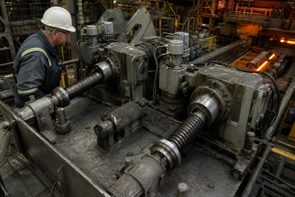
Electromechanical screwdown mechanism: motor, worm gear, screw and nut that set the roll gap of a mill stand
Electromechanical roll adjustment on a mill stand · screw lead per revolution by stand, the worm gearbox between motor and screw, fast-travel and loaded-adjustment drives, and conversion to a hydraulic cylinder
A screwdown stand sets its roll gap with screws: a large threaded screw in each housing post, running in a nut fixed in the housing and pressing down on the top roll chock, turned by a motor through a worm gear. This page is about the mechanical train itself — how far the roll moves per turn of the screw, how the worm gearbox and motors drive it, and how a screwdown stand is converted to hydraulic actuation.
Electromechanical screwdown (roll-adjusting) mechanisms of rolling mill stands: screws and housing nuts, worm gear sets and gearboxes, the motors and clutches that drive them, and their conversion to hydraulic cylinders. Hydraulic gap control systems with servo valves, position transducers and Level 1 position and force control are covered on the Heavy-duty rolling mill hydraulic gap control system page; the hydraulic screwdown cylinders and oil-metering hardware that replace or supplement screws on the Hydraulic screwdown cylinder of a rolling mill page; the transducers mounted on screwdown and gap cylinders on the Position transducer for rolling mill hydraulic cylinders page; the housing that carries the nuts on the Rolling mill housing page; the complete stand on the Heavy-duty rolling mill stand page.
CNFX editorial research · Sources checked October 12, 2026 · 4 sources
How far the roll moves per screw turn: 0.4 inch on the first roughing stand, 0.010 inch on the last finishing stand
US patent 3,433,037 (G. E. Lemon, filed 1966) describes a ten-stand strip mill whose screws are given different leads so that each stand reaches its setting in a similar number of turns: the four roughing stands' screws move the top work roll 0.4, 0.3, 0.2 and 0.1 inch per revolution, and the six finishing stands' screws 0.015, 0.015, 0.015, 0.013, 0.011 and 0.010 inch per revolution. [1]
The patent's example rolls 4.5-inch material to a gauge of 0.100 inch with the roughing stands set at 7, 7, 7 and 10 revolutions and each finishing stand at ten revolutions, and it pairs each screw with a dial whose hands turn once per screw revolution and a counter for whole turns. [1] Where replacing screws on existing equipment would be difficult and costly, the patent obtains the same ratios by changing the gears between the drive and the screw. [1]
Editorial calculation: the lead on stand S1 is 40 times that on S10 (0.4 / 0.010). A coarse lead moves the roll fast for the large openings of roughing passes; a fine lead gives the small, precise steps the finishing passes need, but needs 40 turns for the roll travel that S1 makes in one.
State, for each stand, the roll opening range, the smallest adjustment step required, and the time allowed to move between pass settings; the screw lead and gear ratio follow from those three.
02
Worm gear sets between the motor and the screw: a 36:1 set with 32-inch centres on a plate mill
Renold Gears supplied screw-down worm gears for a quarto reversing plate mill that rolls slabs up to 300 mm thick: a ratio of 36:1, a centre distance of over 32 inches, a worm shaft nearly two metres long, and a combined worm and wheel weight of 4,850 kg. During rolling the worm gears adjust by sliding on a spline in the worm-wheel hub. [4]
Editorial calculation: at 36:1, each turn of the screw needs 36 turns of the worm; a worm driven at 720 rpm would turn the screw at 20 rpm. Combined with a fine finishing-stand lead such as 0.010 inch per turn from the Lemon patent, that would be 0.2 inch (5.1 mm) of roll travel per minute — an illustration of how ratio and lead multiply, not data for the Renold mill. [4][1]
In the arrangement of US patent 3,494,167 (Blaw-Knox, filed 1968), each screwdown screw advances and retracts in a screwdown nut rigidly fixed in the housing, and is driven through worm shafts meshing with worm gears keyed to the screw shafts. [2]
Give the gear maker the stand's maximum screw load and torque, the shock loads during bite and roll changes, the required screw speed, the centre distance available on the housing top, and whether the two sides must be driven separately or together.
03
Two speeds on one worm shaft: fast travel for roll changes, high torque for loading the rolls
The Blaw-Knox patent separates the two duties of a screwdown drive. A first power means drives the worm shafts at high speed with relatively low torque to advance or retract the screws rapidly; a second power means drives the same worm shafts at low speed and high torque through a speed-reducing train and a clutch, to load the rolls and adjust that load during rolling. [2]
Editorial note: the same split shows up in any screwdown drive specification — a travel speed for opening the stand and a separate, much lower speed and torque rating for positioning under load — and the side-to-side coupling decides whether the operator can correct roll tilt by turning one screw alone.
Motors on each side run separately, or coupled to run in unison
Two motors on one shaft line, joined by a clutch [2]
04
Converting a screwdown stand to hydraulic actuation while keeping the housing nut
US patent 4,007,618 (Ritter Engineering, filed 1976) describes retrofitting hydraulic roll actuation to a screwdown mill without cutting into the mill window: a hydraulic cylinder replaces an exterior housing element over the opening that held the screw, and an externally threaded piston-rod sleeve in that opening screws into the original screwdown nut, which then carries the reaction force into the frame. [3]
The patent gives the reasons for the conversion — to remove the inefficiencies of the mechanical screw arrangement and gain the fast response of hydraulics — and states that fitting the cylinder inside the mill window, above the top backup chock or below the bottom one, imposes severe design restraints. Keeping the existing load-carrying frame, it argues, leaves the mill's original load capacity unchanged. [3]
Editorial note: before choosing between keeping the screws, adding a short-stroke cylinder under them, or replacing them, ask for the condition of the housing nuts and the screw threads, since in this retrofit the original nut becomes a structural part of the hydraulic system.
05
What to send for a screwdown mechanism
Paste it into your enquiry below or into an email to a maker, then replace every bracket.
Mill: [type; stand position (roughing or finishing); housing drawing]
Loads: [maximum rolling force per screw; shock at bite]
Travel: [roll opening range; smallest step; time between passes]
Screw and nut: [diameter; lead; nut material; existing or new]
Worm drive: [ratio; centre distance; separate or coupled sides]
Motors: [fast travel and loading duties; clutches; brakes]
Position indication: [dial, counter or encoder]
Hydraulic option: [conversion or cylinder under the screw]
Explore company information and manufacturing capabilities, then discuss the scope of your project with a relevant supplier.
Share this page
Compiled and source-reviewed by the CNFX editorial team.
Each manufacturer above links to the page on that company's own website where the product is listed, with the date we checked it. How we source and review
· Page last updated 13 October 2026
Buyer questions
Why do roughing and finishing stands use different screw leads?
US patent 3,433,037 gives roughing-stand screws 0.4 to 0.1 inch per turn and finishing-stand screws 0.015 to 0.010 inch, so each stand reaches its setting in a similar number of turns. [1]
What gear ratio do screwdown worm gears use?
Renold supplied a 36:1 screw-down worm set with over 32 inches of centre distance for a quarto reversing plate mill. [4]
Why do some screwdowns have two motors per worm shaft?
A Blaw-Knox patent uses a high-speed, low-torque drive for rapid travel and a low-speed, high-torque drive through a reducer and clutch for loading the rolls. [2]
Can a screwdown mill be converted to hydraulic gap control?
US patent 4,007,618 fits a hydraulic cylinder over the screw opening, with a threaded sleeve engaging the original screwdown nut to carry the load. [3]
Sources and what still needs a direct check
Sources checked 2026-10-12. Screw leads by stand come from US patent 3,433,037; the twin-speed worm drive from a Blaw-Knox patent; the hydraulic retrofit from a Ritter Engineering patent; the 36:1 worm gear set from Renold Gears' project report as published by MINING.COM.