Editorial Technical Reference

CIP Spray System

This page explains how CIP Spray System is classified within Beverage Manufacturing. Technical values and manufacturer relationships are research references; confirm the current specification and supplier evidence for each order.

Technical Definition & Core Assembly

A spray system integrated within the Automated Wort Clarification Separator for automated cleaning-in-place (CIP) operations.

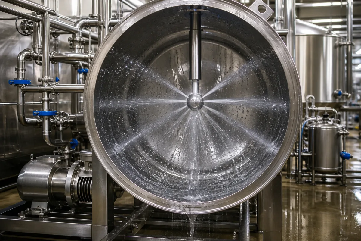
Representative product image. Confirm appearance and specifications with the manufacturer.

Product Specifications

Technical details and manufacturing context for CIP Spray System

Definition
The CIP Spray System is a critical component of the Automated Wort Clarification Separator, designed to perform automated cleaning and sanitization without disassembly. It consists of strategically positioned spray nozzles that distribute cleaning and sanitizing solutions (e.g., caustic, acid, sanitizer) throughout the interior surfaces of the separator vessel and associated piping to remove wort residues, proteins, and microorganisms, ensuring hygiene and preventing cross-contamination between batches. The system operates by pumping cleaning fluids from a central CIP unit through a network of pipes to spray nozzles (typically rotating or static) mounted inside the separator. These nozzles create high-impact jets or spray patterns that cover all internal surfaces. The cleaning cycle is automated and follows a programmed sequence: pre-rinse with water, caustic wash, intermediate rinse, acid wash (if needed), final rinse, and sanitization, with controlled temperature, concentration, and time for each phase. The system is constructed from stainless steel (AISI 304/316L) and food-grade elastomers (e.g., EPDM, PTFE) to withstand harsh cleaning chemicals and high temperatures. Key parameters include an operating pressure of 1.0–1.6 MPa, a flow rate of 15–60 m³/h per nozzle, full 360° spray coverage, and an adjustable spray angle of 70–110°. The nozzle material is 316L stainless steel (ASTM A240), and the body material is 304 stainless steel (ASTM A240). The system operates within a temperature range of 4°C to 95°C, with an electrical supply of 24 V DC (±10%) and power consumption of 12–24 W. It has an ingress protection rating of IP65 (IEC 60529), connection sizes of DN25–DN50 (ISO 1127), and a weight of 5–12 kg depending on configuration. Always verify model-specific values and standards with the legal manufacturer or supplier.
Working Principle
The system operates by pumping cleaning fluids from a central CIP unit through a network of pipes to spray nozzles (typically rotating or static) mounted inside the separator. These nozzles create high-impact jets or spray patterns that cover all internal surfaces. The cleaning cycle is automated and follows a programmed sequence: pre-rinse with water, caustic wash, intermediate rinse, acid wash (if needed), final rinse, and sanitization, with controlled temperature, concentration, and time for each phase.
Common Materials
Stainless Steel (AISI 304/316L), Food-grade elastomers (e.g., EPDM, PTFE)
Technical Parameters
ParameterTypical rangeNotes & selection driver
Flow Rate15–60 m³/hPer spray nozzle at operating pressure
Spray Coverage360 °Full 360° coverage for complete cleaning
Spray Angle70–110 °Adjustable to optimize cleaning
Nozzle Material316LStainless steel for corrosion resistanceASTM A240
Body Material304Stainless steel for durabilityASTM A240
Max Operating Temperature95 °CFor CIP solutions
Min Operating Temperature4 °CFor cold cleaning
Electrical Supply24 ±10% V DCFor control valve actuator
Power Consumption12–24 WFor actuator and sensors
Ingress ProtectionIP65Dust-tight and protected against water jetsIEC 60529
Connection SizeDN25–DN50Tri-clamp or weld endsISO 1127
Weight5–12 kgDepending on configuration

Ranges are indicative industry figures for RFQ preparation, not a supplier commitment. Confirm every value and standard with the legal manufacturer before ordering.

Components / BOM
  • Spray Nozzle
    Distributes cleaning fluid in a specific pattern (e.g., full cone, hollow cone) to cover internal surfaces.
    Material: Stainless Steel
  • Manifold/Piping
    Channels cleaning fluids from the CIP supply to the spray nozzles.
    Material: Stainless Steel
  • Mounting Assembly
    Secures the spray nozzle(s) at the optimal position inside the separator vessel.
    Material: Stainless Steel
  • Cycle Control
    Runs the pre-rinse→caustic→rinse→acid→final-rinse→sanitize sequence at the set temperature, concentration and time.

Industrial Ecosystem & Supply Chain Structure

Complementary Systems
Downstream Applications
Specialized Tooling

Application Fit & Sizing Matrix

Operational Limits
ph range: 2-12 for chemical compatibility
pressure: Max 6 bar (87 psi) operating pressure, 10 bar (145 psi) test pressure
flow rate: 10-50 m³/h per spray nozzle, adjustable via control system
temperature: 5°C to 95°C (operating), up to 140°C for short-term sterilization
slurry concentration: Up to 15% solids by weight for effective cleaning
Media Compatibility
✓ Wort and beer residues (protein, hop, yeast) ✓ Standard CIP chemicals (caustic, acid, sanitizer solutions) ✓ Food-grade lubricants and process water
Unsuitable: Highly abrasive slurries with >15% solids or containing sharp particulate matter
Sizing Data Required
  • Clarifier vessel diameter and geometry
  • Required cleaning cycle time and frequency
  • Available CIP supply pressure and flow capacity

Reliability & Engineering Risk Analysis

Failure Mode & Root Cause
Nozzle clogging
Cause: Accumulation of mineral deposits, biofilm, or product residues due to inadequate water quality, insufficient chemical concentration, or irregular cleaning cycles.
Seal/gasket degradation
Cause: Chemical attack from aggressive CIP solutions (e.g., caustic, acid), thermal cycling, or mechanical wear from pressure fluctuations, leading to leaks and spray pattern disruption.
Maintenance Indicators
  • Irregular or asymmetric spray patterns observed during operation, indicating partial clogging or nozzle wear.
  • Audible hissing or dripping sounds at connection points, suggesting seal failure or leaks under pressure.
Engineering Tips
  • Implement routine nozzle inspection and cleaning schedules using appropriate tools (e.g., soft brushes, approved chemicals) to prevent buildup and maintain optimal spray coverage.
  • Use compatible, chemically resistant seals/gaskets (e.g., EPDM, PTFE) and monitor CIP solution concentration/temperature to minimize degradation and extend component life.

Indicative industry ranges for design and RFQ preparation. Confirm the exact figures and applicable standard with the manufacturer before specifying.

Compliance & Manufacturing Standards

Applicable Standards
ISO 2852: Stainless steel tube fittings for the food industry ANSI/ASME BPE: Bioprocessing equipment DIN 11850: Stainless steel tubes for the food, chemical and pharmaceutical industry

Quoted from the published standard.

Manufacturing Precision
  • Surface finish: Ra ≤ 0.8 μm for product contact surfaces
  • Weld seam alignment: ±0.5 mm maximum deviation
Quality Inspection
  • Pressure test: 1.5x maximum working pressure for 30 minutes
  • Surface roughness verification using profilometer

Manufacturers of CIP Spray System

Manufacturer profiles associated with CIP Spray System.

Sourcing CIP Spray System from China?
Tell us your specification and target quantity — we will match it against manufacturer records and come back with the factories that fit.
Request manufacturers We manufacture this

Manufacturer listings support early research and capability understanding. They are not certification, ranking, or transaction guarantees.

Technical documentation
Request current drawings, revision history, and a signed specification sheet.
Manufacturing capability
Verify equipment lists, process limits, capacity, and representative production evidence.
Inspection readiness
Confirm test methods, calibrated equipment, sampling plans, and traceable reports.
Supplier transparency
Check the legal entity, factory address, ownership, certifications, and direct contacts.

CNFX does not score or rank suppliers. Buyers must verify all claims and documents with the legal manufacturer before ordering.

Supply Chain Compatible Machinery & Devices

Automated Beverage Container Leak Detection System

The Automated Beverage Container Leak Detection System is an industrial device designed for integration into bottling or canning lines.

Explore Specs →
Automated Beverage Container Depalletizing Machine

Industrial machine that automatically removes beverage containers from pallets for production line feeding

Explore Specs →
Regeneration Section

A dedicated section within an industrial system designed to restore or renew the functional properties of materials, media, or components through controlled processes.

Explore Specs →
High-Speed Rotary Bottle Filling Machine

Automated industrial machine for precise liquid filling of beverage containers at high production rates.

Explore Specs →

Frequently Asked Questions

What is the operating pressure range of the CIP Spray System?

The operating pressure is 1.0–1.6 MPa. Always confirm the exact pressure for your specific model with the manufacturer.

What materials are used in the construction?

The system uses stainless steel AISI 304/316L for wetted parts and food-grade elastomers such as EPDM or PTFE for seals. The nozzle material is 316L stainless steel (ASTM A240), and the body is 304 stainless steel (ASTM A240).

What is the maximum operating temperature?

The maximum operating temperature is 95°C, suitable for hot CIP solutions. The minimum is 4°C for cold cleaning. Verify temperature limits for your specific application.

What are the electrical requirements?

The electrical supply is 24 V DC (±10%) for the control valve actuator, with a power consumption of 12–24 W for the actuator and sensors. The ingress protection rating is IP65 (IEC 60529).

Data Basis

Editorial classification, named public sources where available, and source-reviewed manufacturer records.

Preliminary Technical Classification
This page supports structured research, RFQ preparation, and supplier evaluation. It does not replace buyer-led supplier qualification, standards review, or technical approval.
Buyer enquiry

Request manufacturing insight for CIP Spray System

Ask for use case, specification boundaries, supplier type, and RFQ preparation information for this product.

Where it goes
Straight to the CNFX editorial desk, and to the manufacturer if this product is linked to a claimed profile. Nothing is broadcast to a supplier list.
Your details stay here
We do not sell or rent enquiry data, and we do not add you to a mailing list. Used only to answer this request.
No commission, no middleman
CNFX is a directory. We take no cut of any order and never negotiate on a supplier's behalf.
What we don't claim
A listing is not an endorsement. Qualify every supplier and verify every figure yourself before ordering.

Your business information is used only to process this request.

Thank you! Your message has been sent. We'll respond within 1–3 business days.
Sorry, we couldn't send your message. Please try again, or email us at contact@cnfx.com.

Need to Manufacture CIP Spray System?

Compare manufacturer profiles with relevant product and process capability.

Previous Product
Vacuum Gripper End-Effector
Last Product
Get QuotesChat