Editorial Technical Reference

Automated Control System

This page explains how Automated Control System is classified within Chemical Manufacturing. Technical values and manufacturer relationships are research references; confirm the current specification and supplier evidence for each order.

Technical Definition & Core Assembly

A computerized system that monitors and regulates process variables in continuous flow chemical synthesis to maintain optimal reaction conditions.

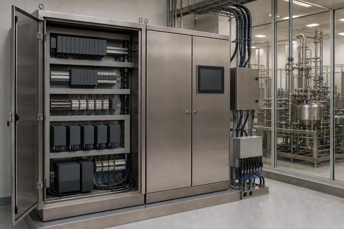
Representative product image. Confirm appearance and specifications with the manufacturer.

Product Specifications

Technical details and manufacturing context for Automated Control System

Definition
The Automated Control System is an integrated hardware and software solution designed for continuous flow chemical synthesis systems. It automatically controls critical process parameters including temperature, pressure, flow rates, pH, and reactant concentrations through real-time monitoring, feedback loops, and automated adjustments to ensure consistent product quality, safety, and efficiency. The system continuously monitors process variables using sensors such as temperature probes, pressure transmitters, flow meters, and analytical instruments. It compares readings against setpoints and automatically adjusts control elements like valves, pumps, heaters, and coolers via programmable logic controllers (PLCs) and distributed control systems (DCS). This closed-loop control maintains desired reaction conditions throughout the continuous synthesis process. The system is housed in stainless steel enclosures and comprises electronic components, industrial-grade wiring, and polymer insulation. Typical parameters include control accuracy of ±0.5%, response time ≤100 ms, operating temperature range -40 to 85 °C, operating pressure 1.0–1.6 MPa, input/output signals of 4–20 mA (per IEC 60381), supply voltage 24 V DC ±10%, power consumption ≤15 W, ingress protection IP54–IP65 (per IEC 60529), communication protocol Modbus RTU (per IEC 61158), 32–128 I/O points, and weight 15–25 kg. These values are reference ranges and must be verified for the specific model and application. The system is intended for use in chemical manufacturing facilities. Buyers should confirm model-specific specifications, standards compliance, and installation requirements with the legal manufacturer or supplier before procurement.
Working Principle
The system operates by continuously sampling process variables through sensors. These signals are transmitted to a controller (PLC or DCS) that compares them to user-defined setpoints. Any deviation triggers an output signal to actuators, such as control valves or variable-speed pumps, to adjust the process. The control loop runs at a frequency that ensures response times of ≤100 ms for fast-acting valves. The system uses standard 4–20 mA analog signals for both input and output, and communicates via Modbus RTU for integration with higher-level systems. The controller executes PID or similar algorithms to maintain stability. The system is powered by a 24 V DC supply and consumes ≤15 W. It is designed for indoor or outdoor installation with IP54–IP65 protection. The number of I/O points can be configured from 32 to 128 depending on process complexity.
Common Materials
Stainless steel enclosures, Electronic components, Industrial-grade wiring, Polymer insulation
Technical Parameters
ParameterTypical rangeNotes & selection driver
Control Accuracy±0.5 %Typical for process control loops
Response Time≤100 msFor fast-acting control valves
Operating Temperature-40–85 °CElectronics enclosure rating
Input Signal4–20 mAStandard analog signalIEC 60381
Output Signal4–20 mAFor valve positioningIEC 60381
Supply Voltage24 ±10% V DCTypical industrial DC supply
Power Consumption≤15 WFor controller and I/O modules
Ingress ProtectionIP54–IP65For indoor/outdoor installationIEC 60529
Communication ProtocolModbus RTUCommon for industrial automationIEC 61158
Number of I/O Points32–128Configurable based on process
Weight15–25 kgFor control cabinet

Ranges are indicative industry figures for RFQ preparation, not a supplier commitment. Confirm every value and standard with the legal manufacturer before ordering.

Components / BOM
  • Programmable Logic Controller
    Executes control algorithms and logic for automated process regulation
    Material: Electronic components in metal enclosure
  • Human-Machine Interface
    Provides operators with visualization, monitoring, and manual override capabilities
    Material: Touchscreen display with protective glass
  • Input/Output Modules
    Interface between sensors/actuators and the control processor
    Material: Electronic circuit boards with connectors
  • Communication Network
    Enables data exchange between system components and external systems
    Material: Ethernet cables and network switches

Industrial Ecosystem & Supply Chain Structure

Complementary Systems
Downstream Applications
Specialized Tooling

Application Fit & Sizing Matrix

Operational Limits
pressure: 0 to 100 bar
flow rate: 0.1 to 1000 L/min
temperature: -40°C to +85°C
slurry concentration: Up to 40% solids by weight
Media Compatibility
✓ Aqueous solutions ✓ Organic solvents (e.g., methanol, acetone) ✓ Corrosion-resistant alloys (e.g., Hastelloy, 316L stainless steel)
Unsuitable: Highly abrasive slurries with >40% solids or corrosive media exceeding pH <2 or >12
Sizing Data Required
  • Maximum process flow rate (L/min)
  • Required pressure drop across the system (bar)
  • Desired control accuracy (±% of setpoint)

Reliability & Engineering Risk Analysis

Failure Mode & Root Cause
Sensor Drift/Calibration Loss
Cause: Environmental factors (temperature, humidity, vibration), aging components, or electromagnetic interference causing sensors to provide inaccurate readings, leading to improper control actions.
Communication Protocol Failure
Cause: Network congestion, cable degradation, incompatible firmware updates, or electromagnetic interference disrupting data exchange between PLCs, HMIs, and field devices, causing system instability or shutdown.
Maintenance Indicators
  • Intermittent or persistent alarm activations on the HMI (Human-Machine Interface) indicating sensor faults, communication errors, or out-of-range parameters.
  • Unusual audible noises from control cabinets (e.g., buzzing from relays, clicking from solenoids) or erratic equipment behavior (e.g., motors starting/stopping unexpectedly, valves cycling improperly).
Engineering Tips
  • Implement a predictive maintenance program using condition monitoring tools (e.g., thermal imaging for electrical connections, vibration analysis for motors) and regular calibration schedules for sensors and transmitters to detect issues before failure.
  • Ensure robust environmental controls (e.g., proper cabinet sealing, temperature/humidity regulation, EMI shielding) and maintain updated documentation of network topology, firmware versions, and spare parts to reduce downtime during repairs.

Indicative industry ranges for design and RFQ preparation. Confirm the exact figures and applicable standard with the manufacturer before specifying.

Compliance & Manufacturing Standards

Applicable Standards
ISO 13849-1: Safety of machinery - Safety-related parts of control systems ANSI/ISA-88: Batch Control CE Marking: Directive 2006/42/EC (Machinery Directive)

Quoted from the published standard.

Manufacturing Precision
  • Positioning Accuracy: +/-0.005mm
  • Repeatability: +/-0.001mm
Quality Inspection
  • Functional Safety Test (PL/SIL verification)
  • Environmental Stress Screening (Temperature/Humidity Cycling)

Manufacturers of Automated Control System

Manufacturer profiles associated with Automated Control System.

Sourcing Automated Control System from China?
Tell us your specification and target quantity — we will match it against manufacturer records and come back with the factories that fit.
Request manufacturers We manufacture this

Manufacturer listings support early research and capability understanding. They are not certification, ranking, or transaction guarantees.

Technical documentation
Request current drawings, revision history, and a signed specification sheet.
Manufacturing capability
Verify equipment lists, process limits, capacity, and representative production evidence.
Inspection readiness
Confirm test methods, calibrated equipment, sampling plans, and traceable reports.
Supplier transparency
Check the legal entity, factory address, ownership, certifications, and direct contacts.

CNFX does not score or rank suppliers. Buyers must verify all claims and documents with the legal manufacturer before ordering.

Supply Chain Compatible Machinery & Devices

Automated Batch Crystallization System

Automated system for controlled crystallization of chemical compounds in batch processes.

Explore Specs →
Automated pH Monitoring and Dosing System

Automated system for continuous pH monitoring and chemical dosing in process streams.

Explore Specs →
Automated Powder Dispensing and Blending System

Automated system for precise dispensing and homogeneous blending of powdered chemicals.

Explore Specs →
Automated Viscosity Control and Mixing System

The Automated Viscosity Control and Mixing System is an industrial automation solution designed for continuous monitoring and adjustment of viscosity in chemical mixing and blending operations.

Explore Specs →

Frequently Asked Questions

What process variables does the Automated Control System regulate?

The system regulates temperature, pressure, flow rates, pH, and reactant concentrations in continuous flow chemical synthesis. It uses sensors to monitor these variables and adjusts control elements to maintain setpoints.

What are the typical electrical and communication specifications?

Typical specifications include a 24 V DC supply voltage (±10%), power consumption ≤15 W, input and output signals of 4–20 mA per IEC 60381, and communication via Modbus RTU per IEC 61158. These are reference values; confirm with the manufacturer for the specific model.

What environmental conditions can the system withstand?

The system is rated for operating temperatures from -40 to 85 °C and has ingress protection of IP54–IP65 per IEC 60529, making it suitable for indoor or outdoor installation. The operating pressure range is 1.0–1.6 MPa.

How should I verify the system's compliance with standards?

The listed standards (e.g., IEC 60381, IEC 60529, IEC 61158) are procurement references. You must request certificates or test reports from the legal manufacturer or supplier to confirm that the specific model meets these standards for your application.

Data Basis

Editorial classification, named public sources where available, and source-reviewed manufacturer records.

Preliminary Technical Classification
This page supports structured research, RFQ preparation, and supplier evaluation. It does not replace buyer-led supplier qualification, standards review, or technical approval.
Buyer enquiry

Request manufacturing insight for Automated Control System

Ask for use case, specification boundaries, supplier type, and RFQ preparation information for this product.

Where it goes
Straight to the CNFX editorial desk, and to the manufacturer if this product is linked to a claimed profile. Nothing is broadcast to a supplier list.
Your details stay here
We do not sell or rent enquiry data, and we do not add you to a mailing list. Used only to answer this request.
No commission, no middleman
CNFX is a directory. We take no cut of any order and never negotiate on a supplier's behalf.
What we don't claim
A listing is not an endorsement. Qualify every supplier and verify every figure yourself before ordering.

Your business information is used only to process this request.

Thank you! Your message has been sent. We'll respond within 1–3 business days.
Sorry, we couldn't send your message. Please try again, or email us at contact@cnfx.com.

Need to Manufacture Automated Control System?

Compare manufacturer profiles with relevant product and process capability.

Previous Product
Twin-Screw Polymer Compounding Extruder
Last Product
Get QuotesChat