Editorial Technical Reference

Burner System

This page explains how Burner System is classified within Chemical Manufacturing. Technical values and manufacturer relationships are research references; confirm the current specification and supplier evidence for each order.

Technical Definition & Core Assembly

A combustion system that provides controlled heat input to the gas reforming process.
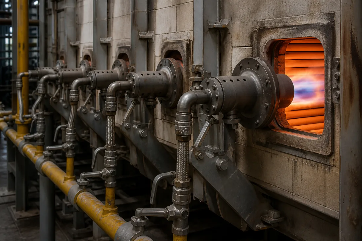
Representative product image. Confirm appearance and specifications with the manufacturer.

Product Specifications

Technical details and manufacturing context for Burner System

Definition
The burner system is a critical component of the Gas Reforming Unit responsible for generating the high-temperature heat required for the endothermic reforming reactions. It precisely controls fuel combustion to maintain optimal temperature profiles within the reformer tubes, ensuring efficient conversion of hydrocarbons into synthesis gas (syngas). The system typically operates with natural gas or process off-gas as fuel, mixed with air or oxygen in a controlled ratio to produce a stable flame. Heat is transferred to the reformer tubes through radiation and convection, and advanced control loops adjust fuel/air ratios based on temperature sensors to maintain precise thermal conditions while minimizing emissions. Key parameters include thermal capacity ranging from 0.5 to 10 MW, fuel gas pressure between 0.1 and 0.5 MPa, combustion air temperature from 20 to 400 °C, flue gas O2 content of 2–5%, NOx emission ≤80 mg/Nm³ (per EN 676), turndown ratio of 10:1, control accuracy ±1%, supply voltage 220/380 V AC (per IEC 60038), power consumption 1.5–5.5 kW, operating temperature -20 to 60 °C, ingress protection IP54–IP65 (per IEC 60529), burner body material SS 304/316 (per ASTM A240), and weight 150–800 kg. Materials on file include high-temperature alloy steel, refractory ceramics, and heat-resistant stainless steel. These values are reference ranges and must be verified for the specific model and application with the legal manufacturer or supplier. The burner system is designed for integration into chemical manufacturing processes, particularly in reforming units, and its selection depends on reformer duty, fuel type, and emission requirements. Proper installation, commissioning, and maintenance are essential for safe and efficient operation. Verification questions should address compatibility with existing control systems, compliance with local regulations, and availability of spare parts. Maintenance signals include flame instability, increased emissions, or temperature deviations, which may indicate wear or misadjustment. Failure boundaries include operation outside specified pressure or temperature limits, which can lead to flame instability or equipment damage.
Working Principle
The burner system mixes fuel (typically natural gas or process off-gas) with air or oxygen in a controlled ratio, then ignites the mixture to produce a stable flame. Heat is transferred to the reformer tubes through radiation and convection. Modern systems use advanced control loops to adjust fuel/air ratios based on temperature sensors, maintaining precise thermal conditions while minimizing emissions.
Common Materials
High-temperature alloy steel, Refractory ceramics, Heat-resistant stainless steel
Technical Parameters
ParameterTypical rangeNotes & selection driver
Thermal Capacity0.5–10 MWMatches reformer duty
Fuel Gas Pressure0.1–0.5 MPaBelow 0.1 MPa may cause flame instability
Combustion Air Temperature20–400 °CHigher improves efficiency
Flue Gas O2 Content2–5 %Optimal for combustion control
NOx Emission≤80 mg/Nm³Complies with local regulationsEN 676
Turndown Ratio10:1Flexible load changes
Control Accuracy±1 %Maintains temperature stability
Supply Voltage220/380 V ACThree-phase or single-phaseIEC 60038
Power Consumption1.5–5.5 kWIncludes fan and controls
Operating Temperature-20–60 °CAmbient for control cabinet
Ingress ProtectionIP54–IP65Protects against dust and waterIEC 60529
Burner Body Material304/316 SSCorrosion resistanceASTM A240
Weight150–800 kgDepends on capacity

Ranges are indicative industry figures for RFQ preparation, not a supplier commitment. Confirm every value and standard with the legal manufacturer before ordering.

Components / BOM
  • Burner Head
    Mixes fuel and air, creates stable flame pattern
    Material: High-temperature alloy steel
  • Fuel Nozzle
    Atomizes and distributes fuel into combustion chamber
    Material: Stainless steel with ceramic tip
  • Ignition System
    Provides spark or pilot flame for burner startup
    Material: Ceramic insulated electrodes
  • Flame Detector
    Monitors flame presence for safety interlock
    Material: UV/IR sensor with quartz lens
  • Air Register
    Controls primary and secondary air flow to burner
    Material: Cast iron with heat-resistant coating
  • Fuel-Air Ratio Controller Optional
    Trims the fuel/air ratio from tube-temperature feedback to hold heat input and cut emissions.

Applied To / Applications

This component is essential for the following industrial systems and equipment:

Industrial Ecosystem & Supply Chain Structure

Complementary Systems
Downstream Applications
Specialized Tooling

Application Fit & Sizing Matrix

Operational Limits
pressure: Up to 30 bar (max operating pressure)
flow rate: 100-5000 Nm³/h (natural gas equivalent)
temperature: 800-1200°C (typical operating range)
slurry concentration: Not applicable (gas reforming typically uses gaseous feed)
Media Compatibility
✓ Natural gas reforming ✓ Hydrogen production ✓ Syngas generation
Unsuitable: High particulate/solid fuel environments (e.g., coal dust, biomass with high ash content)
Sizing Data Required
  • Required heat input (kW or BTU/hr)
  • Reformer tube diameter and arrangement
  • Available fuel gas composition and pressure

Reliability & Engineering Risk Analysis

Failure Mode & Root Cause
Flame instability
Cause: Inadequate air-fuel ratio, clogged fuel nozzles, or improper burner alignment leading to incomplete combustion and potential flameout.
Thermal fatigue cracking
Cause: Cyclic heating and cooling stresses, especially during frequent startups/shutdowns, causing cracks in burner tiles, refractory, or metal components.
Maintenance Indicators
  • Yellow or flickering flame (instead of steady blue flame)
  • Unusual pulsating noises or rumbling sounds during operation
Engineering Tips
  • Implement regular combustion analysis and tuning to maintain optimal air-fuel ratio, preventing incomplete combustion and reducing thermal stresses.
  • Establish controlled startup/shutdown procedures with proper purge cycles to minimize thermal shock and extend refractory/component life.

Indicative industry ranges for design and RFQ preparation. Confirm the exact figures and applicable standard with the manufacturer before specifying.

Compliance & Manufacturing Standards

Applicable Standards
ISO 23551-1: Safety and control devices for gas burners and gas-burning appliances ANSI Z21.13: Gas-Fired Low Pressure Steam and Hot Water Boilers CE EN 676: Automatic forced draught gas burners

Quoted from the published standard.

Manufacturing Precision
  • Nozzle orifice diameter: +/-0.01mm
  • Flame retention head concentricity: 0.05mm TIR
Quality Inspection
  • Leak test: 1.5x working pressure hydrostatic/pneumatic
  • Flame stability test: Verification of stable ignition and combustion across operating range

Manufacturers of Burner System

Manufacturer profiles associated with Burner System.

Sourcing Burner System from China?
Tell us your specification and target quantity — we will match it against manufacturer records and come back with the factories that fit.
Request manufacturers We manufacture this

Manufacturer listings support early research and capability understanding. They are not certification, ranking, or transaction guarantees.

Technical documentation
Request current drawings, revision history, and a signed specification sheet.
Manufacturing capability
Verify equipment lists, process limits, capacity, and representative production evidence.
Inspection readiness
Confirm test methods, calibrated equipment, sampling plans, and traceable reports.
Supplier transparency
Check the legal entity, factory address, ownership, certifications, and direct contacts.

CNFX does not score or rank suppliers. Buyers must verify all claims and documents with the legal manufacturer before ordering.

Supply Chain Compatible Machinery & Devices

Automated Batch Crystallization System

Automated system for controlled crystallization of chemical compounds in batch processes.

Explore Specs →
Automated pH Monitoring and Dosing System

Automated system for continuous pH monitoring and chemical dosing in process streams.

Explore Specs →
Automated Powder Dispensing and Blending System

Automated system for precise dispensing and homogeneous blending of powdered chemicals.

Explore Specs →
Automated Viscosity Control and Mixing System

The Automated Viscosity Control and Mixing System is an industrial automation solution designed for continuous monitoring and adjustment of viscosity in chemical mixing and blending operations.

Explore Specs →

Frequently Asked Questions

What is the typical thermal capacity range for this burner system?

The thermal capacity is listed as 0.5–10 MW, matching reformer duty. However, the exact value depends on the specific model and application, so it must be confirmed with the manufacturer.

What fuel gas pressure is required for stable operation?

The fuel gas pressure range is 0.1–0.5 MPa. Below 0.1 MPa may cause flame instability, so ensure the supply meets this requirement.

What are the NOx emission limits?

The NOx emission is ≤80 mg/Nm³, complying with EN 676. This is a reference value; actual emissions depend on operating conditions and must be verified for your installation.

What materials are used in the burner construction?

Materials on file include high-temperature alloy steel, refractory ceramics, and heat-resistant stainless steel. The burner body material is specified as SS 304/316 per ASTM A240, but confirm with the supplier for your specific model.

Data Basis

Editorial classification, named public sources where available, and source-reviewed manufacturer records.

Preliminary Technical Classification
This page supports structured research, RFQ preparation, and supplier evaluation. It does not replace buyer-led supplier qualification, standards review, or technical approval.
Buyer enquiry

Request manufacturing insight for Burner System

Ask for use case, specification boundaries, supplier type, and RFQ preparation information for this product.

Where it goes
Straight to the CNFX editorial desk, and to the manufacturer if this product is linked to a claimed profile. Nothing is broadcast to a supplier list.
Your details stay here
We do not sell or rent enquiry data, and we do not add you to a mailing list. Used only to answer this request.
No commission, no middleman
CNFX is a directory. We take no cut of any order and never negotiate on a supplier's behalf.
What we don't claim
A listing is not an endorsement. Qualify every supplier and verify every figure yourself before ordering.

Your business information is used only to process this request.

Thank you! Your message has been sent. We'll respond within 1–3 business days.
Sorry, we couldn't send your message. Please try again, or email us at contact@cnfx.com.

Need to Manufacture Burner System?

Compare manufacturer profiles with relevant product and process capability.

Previous Product
Twin-Screw Polymer Compounding Extruder
Last Product
Get QuotesChat