Editorial Technical Reference

Gas Reforming Unit

This page explains how Gas Reforming Unit is classified within Basic Metal Manufacturing. Technical values and manufacturer relationships are research references; confirm the current specification and supplier evidence for each order.

Technical Definition & Core Assembly

A unit that converts hydrocarbon feedstocks into synthesis gas (syngas) containing hydrogen and carbon monoxide for use in direct reduction iron processes.

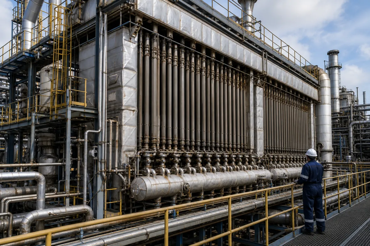
Gas Reforming Unit in a manufacturing environment
Representative product image. Confirm appearance and specifications with the manufacturer.

Product Specifications

Technical details and manufacturing context for Gas Reforming Unit

Definition
The Gas Reforming Unit is a critical component within the Integrated Direct Reduction Iron and Electric Arc Furnace Steelmaking System. It processes natural gas or other hydrocarbon fuels to produce a reducing gas mixture (primarily H₂ and CO) essential for the direct reduction of iron ore in the shaft furnace. This unit enables the substitution of coke with natural gas, reducing carbon emissions in the primary ironmaking stage. The unit typically operates on steam methane reforming (SMR) or autothermal reforming (ATR) principles. In SMR, natural gas reacts with steam over a nickel-based catalyst at high temperatures (700-1000°C) to produce syngas (H₂ + CO). The reaction is endothermic, requiring external heat. The produced syngas is then conditioned (e.g., cooled, purified) before being fed to the direct reduction reactor. Key parameters for selection include syngas capacity (5000–50000 Nm³/h), operating pressure (1.0–1.6 MPa), operating temperature (850–1050°C), pressure drop (≤0.05 MPa), thermal efficiency (65–75%), H2/CO ratio (1.5–2.5), carbon conversion (≥98%), and material grade for reformer tubes (Incoloy 800H, ASTM B409). Auxiliary requirements include electrical power (50–200 kW), control voltage (24 V DC ±10%, IEC 61131-2), ingress protection (IP54–IP65, IEC 60529), footprint (200–1000 m²), and dry weight (50–200 t). The unit interfaces with feedstock supply, steam system, heat recovery, and the direct reduction reactor. Verification questions should address actual process conditions, feedstock composition, and compliance with relevant standards. Maintenance signals include catalyst deactivation, tube wall thinning, and pressure drop increase. Failure boundaries include operating outside temperature/pressure limits or exceeding catalyst life. Always verify model-specific values and standards with the legal manufacturer or supplier.
Working Principle
The unit typically operates on steam methane reforming (SMR) or autothermal reforming (ATR) principles. In SMR, natural gas reacts with steam over a nickel-based catalyst at high temperatures (700-1000°C) to produce syngas (H₂ + CO). The reaction is endothermic, requiring external heat. The produced syngas is then conditioned (e.g., cooled, purified) before being fed to the direct reduction reactor.
Common Materials
Nickel-based catalyst, High-temperature alloy steel (reactor tubes), Refractory lining, Carbon steel (structural)
Technical Parameters
ParameterTypical rangeNotes & selection driver
Syngas Capacity5000–50000 Nm³/hTypical range for DRI plants
Operating Temperature850–1050 °CReformer outlet temperature
Pressure Drop≤0.05 MPaAcross the reformer
Thermal Efficiency65–75 %Based on LHV
H2/CO Ratio1.5–2.5Adjustable via CO2 recycle
Carbon Conversion≥98 %For natural gas feedstock
Material GradeIncoloy 800HReformer tubesASTM B409
Electrical Power50–200 kWFor auxiliaries
Control Voltage24 ±10% V DCFor PLC and sensorsIEC 61131-2
Ingress ProtectionIP54–IP65For electrical enclosuresIEC 60529
Footprint200–1000 Including reformer and heat recovery
Weight50–200 tDry weight

Ranges are indicative industry figures for RFQ preparation, not a supplier commitment. Confirm every value and standard with the legal manufacturer before ordering.

Components / BOM
  • Reformer Reactor
    Houses the catalyst where the reforming reaction occurs under controlled temperature and pressure.
    Material: High-temperature alloy steel (e.g., HK-40, HP-modified)
  • Catalyst Tubes
    Contain the nickel catalyst; designed to withstand high temperatures and thermal stress.
    Material: Centrifugally cast alloy steel
  • Burner System
    Provides the necessary heat for the endothermic reforming reaction in SMR configurations.
    Material: Heat-resistant steel
  • Waste Heat Boiler
    Recovers heat from the hot reformer effluent to generate steam, improving energy efficiency.
    Material: Carbon steel / alloy steel
  • Nickel Catalyst
    The catalyst bed the reforming reaction runs over; a periodically replaced consumable.
    Material: Nickel-based catalyst
  • Syngas Purifier
    Cleans the reformed gas before it goes to the reduction reactor.

Industrial Ecosystem & Supply Chain Structure

Complementary Systems
Downstream Applications
Specialized Tooling

Application Fit & Sizing Matrix

Operational Limits
pressure: 10-40 bar (operating pressure range)
flow rate: Varies by capacity, typically 10,000-500,000 Nm³/h syngas output
temperature: 800-1100°C (typical reforming temperature range)
slurry concentration: Not applicable (gas-phase process)
Media Compatibility
✓ Natural gas feedstock ✓ Naphtha feedstock ✓ Refinery off-gases
Unsuitable: High sulfur content feedstocks (>50 ppm) without pretreatment
Sizing Data Required
  • Required syngas production capacity (Nm³/h)
  • Feedstock composition and flow rate
  • Required hydrogen-to-carbon monoxide ratio in syngas

Reliability & Engineering Risk Analysis

Failure Mode & Root Cause
Catalyst Deactivation
Cause: Poisoning by sulfur compounds, carbon deposition (coking), or sintering due to high-temperature operation exceeding design limits, leading to reduced reforming efficiency and increased pressure drop.
Reformer Tube Failure
Cause: Creep rupture from prolonged exposure to high temperatures (typically 800-950°C) and thermal cycling, exacerbated by internal carburization or hot spots due to flame impingement or catalyst maldistribution.
Maintenance Indicators
  • Abnormal increase in reformer outlet temperature or tube skin temperatures indicating catalyst degradation or flow maldistribution
  • Sudden drop in hydrogen purity or rise in methane slip in product gas, signaling catalyst deactivation or reactor leaks
Engineering Tips
  • Implement rigorous feedstock sulfur removal (<0.5 ppm) and controlled steam-to-carbon ratios to minimize catalyst poisoning and coking, with regular catalyst activity monitoring via temperature profiles and product analysis.
  • Use infrared thermography for continuous reformer tube temperature mapping to detect hot spots early, combined with scheduled decoking cycles and strict adherence to startup/shutdown thermal ramp rates to reduce thermal stress.

Indicative industry ranges for design and RFQ preparation. Confirm the exact figures and applicable standard with the manufacturer before specifying.

Compliance & Manufacturing Standards

Applicable Standards
ASME B31.3 - Process Piping ATEX Directive 2014/34/EU - Equipment for Explosive Atmospheres

Quoted from the published standard.

Manufacturing Precision
  • Pipe Wall Thickness: +/-5% of nominal thickness
  • Flange Flatness: 0.1mm per 300mm diameter
Quality Inspection
  • Hydrostatic Pressure Test
  • Ultrasonic Thickness Testing

Manufacturers of Gas Reforming Unit

Manufacturer profiles associated with Gas Reforming Unit.

Sourcing Gas Reforming Unit from China?
Tell us your specification and target quantity — we will match it against manufacturer records and come back with the factories that fit.
Request manufacturers We manufacture this

Manufacturer listings support early research and capability understanding. They are not certification, ranking, or transaction guarantees.

Share this page
Technical documentation
Request current drawings, revision history, and a signed specification sheet.
Manufacturing capability
Verify equipment lists, process limits, capacity, and representative production evidence.
Inspection readiness
Confirm test methods, calibrated equipment, sampling plans, and traceable reports.
Supplier transparency
Check the legal entity, factory address, ownership, certifications, and direct contacts.

CNFX does not score or rank suppliers. Buyers must verify all claims and documents with the legal manufacturer before ordering.

Supply Chain Compatible Machinery & Devices

Continuous Casting Machine

Industrial machine for solidifying molten metal into continuous billets/blooms/slabs.

Explore Specs →
Vacuum Induction Melting Furnace

Industrial furnace for melting metals under vacuum using electromagnetic induction

Explore Specs →
Electroslag Remelting Furnace

An industrial furnace used in basic metal manufacturing for secondary refining of alloys through the electroslag remelting (ESR) process.

Explore Specs →
Molten Metal Temperature Measurement System

Automated system for continuous temperature monitoring of molten metals during processing.

Explore Specs →

Frequently Asked Questions

What is the typical syngas capacity range for this unit?

According to the directory, the syngas capacity is typically in the range of 5000 to 50000 Nm³/h for DRI plants. However, the exact capacity depends on the specific model and application, so it must be confirmed with the manufacturer.

What operating pressure and temperature are specified?

The operating pressure is listed as 1.0 to 1.6 MPa, and the operating temperature (reformer outlet) is 850 to 1050°C. These values are reference ranges and should be verified for the actual unit.

What materials are used in the reformer tubes?

The reformer tubes are specified as Incoloy 800H, with the standard ASTM B409. This is a high-temperature alloy steel suitable for the reforming environment. Confirm material grade with the supplier.

What are the electrical and control requirements?

Auxiliary electrical power is 50 to 200 kW, and control voltage is 24 V DC ±10% per IEC 61131-2. Ingress protection for electrical enclosures is IP54 to IP65 per IEC 60529. These are typical values; verify for your installation.

Data Basis

Editorial classification, named public sources where available, and source-reviewed manufacturer records.

Preliminary Technical Classification
This page supports structured research, RFQ preparation, and supplier evaluation. It does not replace buyer-led supplier qualification, standards review, or technical approval.
Buyer enquiry

Request manufacturing insight for Gas Reforming Unit

Ask for use case, specification boundaries, supplier type, and RFQ preparation information for this product.

Where it goes
Straight to the CNFX editorial desk, and to the manufacturer if this product is linked to a claimed profile. Nothing is broadcast to a supplier list.
Your details stay here
We do not sell or rent enquiry data, and we do not add you to a mailing list. Used only to answer this request.
No commission, no middleman
CNFX is a directory. We take no cut of any order and never negotiate on a supplier's behalf.
What we don't claim
A listing is not an endorsement. Qualify every supplier and verify every figure yourself before ordering.

Your business information is used only to process this request.

Thank you! Your message has been sent. We'll respond within 1–3 business days.
Sorry, we couldn't send your message. Please try again, or email us at [email protected].

Need to Manufacture Gas Reforming Unit?

Compare manufacturer profiles with relevant product and process capability.

Previous Product
Work Rolls
Last Product
Get QuotesChat