Editorial Technical Reference

Collection Manifold

This page explains how Collection Manifold is classified within Chemical Manufacturing. Technical values and manufacturer relationships are research references; confirm the current specification and supplier evidence for each order.

Technical Definition & Core Assembly

A distribution component that consolidates and directs fluid outputs from multiple microreactors into a single stream or designated outlets.
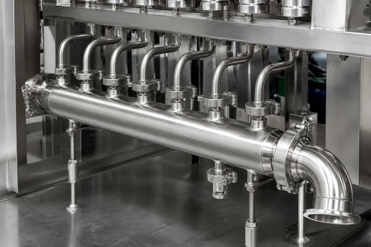
Representative product image. Confirm appearance and specifications with the manufacturer.

Product Specifications

Technical details and manufacturing context for Collection Manifold

Definition
Within a Microreactor Array system, the Collection Manifold serves as a critical fluid-handling component. It is designed to receive the processed fluid outputs from the individual reaction channels or chambers of the array. Its primary function is to efficiently combine these multiple parallel streams into a unified flow for downstream processing, sampling, or analysis, ensuring controlled fluid transfer and minimizing cross-contamination or pressure imbalances between channels. The manifold is typically constructed from materials such as Stainless Steel 316L, PTFE, or Glass, selected for chemical compatibility and cleanability. It features multiple inlet ports (typically 4 to 12) that connect to the microreactor outlets, and one or more central outlet ports with diameters ranging from 6 to 25 mm to match downstream piping. Internal channels or a plenum facilitate mixing or directed flow consolidation, with design considerations for uniform pressure distribution and laminar flow transition. The operating pressure range is 1.0–1.6 MPa, and the operating temperature range is -40 to 85°C. The manifold may incorporate valves or flow restrictors for individual channel control. Key parameters include flow rate (0.5–5 m³/h at max pressure drop), pressure drop (≤0.05 MPa at rated flow), surface finish (≤0.8 μm Ra for cleanability), and leak rate (≤1×10⁻⁶ Pa·m³/s per ISO 15848). Connection type is typically flange per DIN EN 1092-1, with other types on request. Weight ranges from 2 to 8 kg depending on configuration. Always verify model-specific values and standards with the legal manufacturer or supplier before procurement.
Working Principle
The manifold operates by providing a common header or chamber with multiple inlet ports connected to the outlets of the microreactors. Fluid from each reactor enters the manifold, where internal channels or a plenum facilitate mixing or directed flow consolidation. The design ensures uniform pressure distribution and laminar flow transition, guiding the combined fluid to one or more central outlet ports. It may incorporate valves or flow restrictors for individual channel control.
Common Materials
Stainless Steel 316L, PTFE (Polytetrafluoroethylene), Glass
Technical Parameters
ParameterTypical rangeNotes & selection driver
Operating Temperature-40–85 °COutside range, seals may fail
Number of Inlets4–12Customizable per reactor configuration
Outlet Diameter6–25 mmMatches downstream piping
Flow Rate0.5–5 m³/hAt max pressure drop
Pressure Drop≤0.05 MPaAt rated flow
Material316LCorrosion-resistantASTM A240
Surface Finish≤0.8 μm RaFor cleanability
Leak Rate≤1×10⁻⁶ Pa·m³/sHelium leak testISO 15848
Weight2–8 kgDepends on configuration
Connection TypeFlangeOther types on requestDIN EN 1092-1

Ranges are indicative industry figures for RFQ preparation, not a supplier commitment. Confirm every value and standard with the legal manufacturer before ordering.

Components / BOM
  • Manifold Body
    Main structural housing containing internal flow channels that consolidate fluid from inlets.
    Material: Stainless Steel 316L
  • Inlet Port Fittings Part
    Threaded or compression fittings that provide sealed connections to microreactor outlet lines.
    Material: Stainless Steel 316L
  • Outlet Port Part
    Primary discharge connection for the consolidated fluid stream to exit the manifold.
    Material: Stainless Steel 316L
  • Sealing Gaskets/O-Rings Part
    Provide leak-proof seals at port connections and between manifold sections if applicable.
    Material: Viton (FKM) or PTFE
  • Flow Restrictor or Valve Optional
    Trims or shuts one microreactor branch without touching the others.

Applied To / Applications

This component is essential for the following industrial systems and equipment:

Industrial Ecosystem & Supply Chain Structure

Complementary Systems
Downstream Applications
Specialized Tooling

Application Fit & Sizing Matrix

Operational Limits
pressure: 0 to 10 bar (g)
flow rate: Up to 500 L/min total
temperature: -20°C to 200°C
slurry concentration: Up to 30% solids by weight
Media Compatibility
✓ Aqueous process streams ✓ Organic solvents (e.g., ethanol, acetone) ✓ Gas-liquid mixtures
Unsuitable: Highly corrosive acids (e.g., concentrated sulfuric acid, hydrofluoric acid)
Sizing Data Required
  • Total number of microreactor inputs
  • Required total volumetric flow rate
  • Maximum allowable pressure drop across manifold

Reliability & Engineering Risk Analysis

Failure Mode & Root Cause
Fatigue cracking
Cause: Cyclic pressure fluctuations and thermal stresses from process variations, leading to crack initiation at stress concentrators like welds or branch connections.
Corrosion/erosion
Cause: Aggressive fluid chemistry (e.g., H2S, chlorides, abrasive particulates) combined with high flow velocities, causing wall thinning or pitting, especially at elbows and tees.
Maintenance Indicators
  • Visible weeping or droplets at welds/fittings indicating through-wall cracks or seal failure
  • Audible high-frequency whistling or hissing under pressure, suggesting gas leakage or cavitation
Engineering Tips
  • Implement regular ultrasonic thickness (UT) testing at high-risk zones (bends, welds) to monitor wall loss trends and schedule replacements before failure.
  • Install flow straighteners or diffusers upstream to reduce turbulent impingement and erosion at manifold inlets, and ensure proper cathodic protection if buried/exposed.

Indicative industry ranges for design and RFQ preparation. Confirm the exact figures and applicable standard with the manufacturer before specifying.

Compliance & Manufacturing Standards

Applicable Standards
ASME B31.3 (Process Piping) PED 2014/68/EU (Pressure Equipment Directive)

Quoted from the published standard.

Manufacturing Precision
  • Wall Thickness: +/-10% of nominal
  • Flange Flatness: 0.1mm per 300mm diameter
Quality Inspection
  • Hydrostatic Pressure Test
  • Dimensional Verification with CMM

Manufacturers of Collection Manifold

Manufacturer profiles associated with Collection Manifold.

Sourcing Collection Manifold from China?
Tell us your specification and target quantity — we will match it against manufacturer records and come back with the factories that fit.
Request manufacturers We manufacture this

Manufacturer listings support early research and capability understanding. They are not certification, ranking, or transaction guarantees.

Technical documentation
Request current drawings, revision history, and a signed specification sheet.
Manufacturing capability
Verify equipment lists, process limits, capacity, and representative production evidence.
Inspection readiness
Confirm test methods, calibrated equipment, sampling plans, and traceable reports.
Supplier transparency
Check the legal entity, factory address, ownership, certifications, and direct contacts.

CNFX does not score or rank suppliers. Buyers must verify all claims and documents with the legal manufacturer before ordering.

Supply Chain Compatible Machinery & Devices

Automated Batch Crystallization System

Automated system for controlled crystallization of chemical compounds in batch processes.

Explore Specs →
Automated pH Monitoring and Dosing System

Automated system for continuous pH monitoring and chemical dosing in process streams.

Explore Specs →
Automated Powder Dispensing and Blending System

Automated system for precise dispensing and homogeneous blending of powdered chemicals.

Explore Specs →
Automated Viscosity Control and Mixing System

The Automated Viscosity Control and Mixing System is an industrial automation solution designed for continuous monitoring and adjustment of viscosity in chemical mixing and blending operations.

Explore Specs →

Frequently Asked Questions

What materials are available for the Collection Manifold?

The manifold can be made from Stainless Steel 316L, PTFE, or Glass, as listed in the directory. Material selection should be based on chemical compatibility and cleanability requirements for your specific application.

What is the operating pressure range?

The operating pressure range is 1.0–1.6 MPa. Ensure your system operates within this range.

How many inlets can the manifold have?

The number of inlets is customizable per reactor configuration, typically ranging from 4 to 12. Confirm the exact number needed for your microreactor array with the supplier.

What connection types are available?

The standard connection type is flange per DIN EN 1092-1. Other types may be available on request, but you should verify with the manufacturer for your specific needs.

Data Basis

Editorial classification, named public sources where available, and source-reviewed manufacturer records.

Preliminary Technical Classification
This page supports structured research, RFQ preparation, and supplier evaluation. It does not replace buyer-led supplier qualification, standards review, or technical approval.
Buyer enquiry

Request manufacturing insight for Collection Manifold

Ask for use case, specification boundaries, supplier type, and RFQ preparation information for this product.

Where it goes
Straight to the CNFX editorial desk, and to the manufacturer if this product is linked to a claimed profile. Nothing is broadcast to a supplier list.
Your details stay here
We do not sell or rent enquiry data, and we do not add you to a mailing list. Used only to answer this request.
No commission, no middleman
CNFX is a directory. We take no cut of any order and never negotiate on a supplier's behalf.
What we don't claim
A listing is not an endorsement. Qualify every supplier and verify every figure yourself before ordering.

Your business information is used only to process this request.

Thank you! Your message has been sent. We'll respond within 1–3 business days.
Sorry, we couldn't send your message. Please try again, or email us at contact@cnfx.com.

Need to Manufacture Collection Manifold?

Compare manufacturer profiles with relevant product and process capability.

Previous Product
Twin-Screw Polymer Compounding Extruder
Last Product
Get QuotesChat