Editorial Technical Reference

Collection Tank

This page explains how Collection Tank is classified within Chemical Manufacturing. Technical values and manufacturer relationships are research references; confirm the current specification and supplier evidence for each order.

Technical Definition & Core Assembly

A vessel designed to collect and temporarily store recovered solvents within a solvent recovery system.

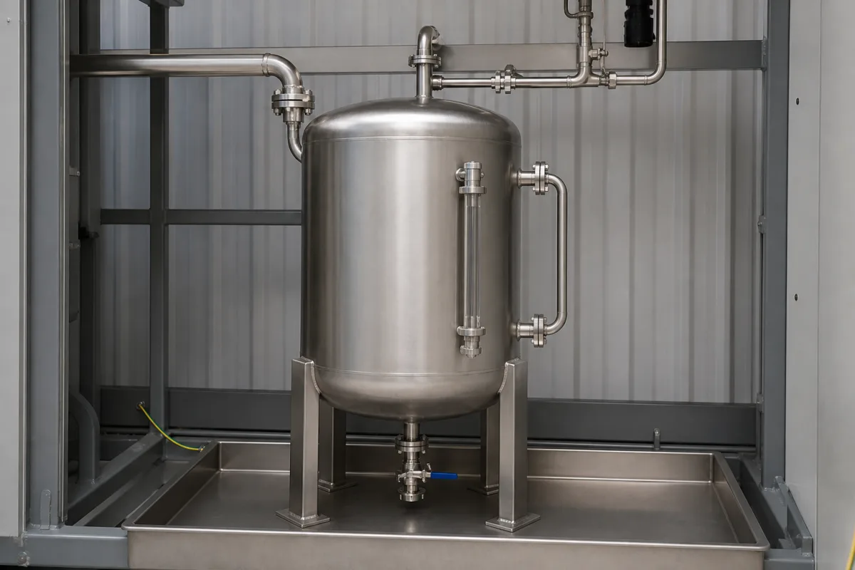
Representative product image. Confirm appearance and specifications with the manufacturer.

Product Specifications

Technical details and manufacturing context for Collection Tank

Definition
The Collection Tank is a critical component of the Solvent Recovery Module, serving as the primary storage vessel for solvents that have been condensed and separated from waste streams. It functions as an intermediate holding container where recovered solvents accumulate before being transferred for purification, reuse, or disposal, ensuring continuous operation of the recovery process. The tank is available in nominal capacities from 500 to 5000 liters, with design pressures ranging from 1.0 to 1.6 MPa (per GB/T 150) and design temperatures from -20°C to 150°C. Materials on file include Stainless Steel 316L, Carbon Steel, and Fiberglass Reinforced Plastic; the material grade (304/316L) should be selected based on solvent corrosivity, with 316L recommended for corrosive solvents. Wall thickness ranges from 6 to 12 mm, and internal surface finish from 0.4 to 0.8 μm Ra (ISO 1302) for high-purity applications. The tank meets a leakage rate of ≤1×10⁻⁶ Pa·m³/s (ISO 15848-1) for volatile organic compounds. Insulation thickness of 50–100 mm is available for temperature maintenance. Empty weight ranges from 200 to 2000 kg, affecting foundation and lifting requirements. Inlet/outlet sizes are DN50–DN150 (ISO 7005) to match piping systems. Level measurement accuracy is ±0.5% FS for reliable inventory control, and corrosion allowance is 1–3 mm (GB/T 150) based on solvent corrosivity. The tank operates by receiving condensed solvent vapors via piping, maintaining the liquid at ambient or controlled temperatures and pressures. Level sensors monitor fill levels to prevent overflows and trigger transfer pumps when capacity thresholds are reached. Agitation or mixing systems may be included to maintain solvent homogeneity. For procurement, verify model-specific values and standards with the legal manufacturer or supplier.
Working Principle
Condensed solvent vapors from the recovery unit are directed into the Collection Tank via piping. The tank maintains the collected liquid at ambient or controlled temperatures and pressures. Level sensors monitor fill levels to prevent overflows and trigger transfer pumps when capacity thresholds are reached. The tank may include agitation or mixing systems to maintain solvent homogeneity.
Common Materials
Stainless Steel 316L, Carbon Steel, Fiberglass Reinforced Plastic
Technical Parameters
ParameterTypical rangeNotes & selection driver
Nominal Capacity500–5000 LSelect based on batch size and recovery rate.
Design Pressure1.0–1.6 MPaHigher pressure for vacuum operation.GB/T 150
Design Temperature-20–150 °CEnsure material compatibility at max temp.
Material304/316L316L for corrosive solvents.ASTM A240
Wall Thickness6–12 mmDepends on pressure and diameter.
Surface Finish (Internal)0.4–0.8 μm RaSmoother finish for high-purity solvents.ISO 1302
Leakage Rate≤1×10⁻⁶ Pa·m³/sFor volatile organic compounds.ISO 15848-1
Insulation Thickness50–100 mmRequired for temperature maintenance.
Weight (Empty)200–2000 kgAffects foundation and lifting requirements.
Inlet/Outlet SizeDN50–DN150Match piping system.ISO 7005
Level Measurement Accuracy±0.5 % FSFor reliable inventory control.
Corrosion Allowance1–3 mmBased on solvent corrosivity.GB/T 150

Ranges are indicative industry figures for RFQ preparation, not a supplier commitment. Confirm every value and standard with the legal manufacturer before ordering.

Components / BOM
  • Tank Body
    The tank shell itself: holds the contents and carries the static and operating loads.
  • Inlet Nozzle Part
    Entry point for condensed solvent from recovery unit
    Material: Stainless Steel
  • Outlet Valve
    Controls discharge of collected solvent to downstream processes
    Material: Stainless Steel
  • Level Sensor
    Monitors solvent volume and prevents overfilling
    Material: Stainless Steel/PVC
  • Pressure Relief Valve
    Safety device to prevent over-pressurization
    Material: Stainless Steel
  • Manhole/Access Port
    Provides access for inspection, cleaning, and maintenance
    Material: Stainless Steel

Applied To / Applications

This component is essential for the following industrial systems and equipment:

Industrial Ecosystem & Supply Chain Structure

Complementary Systems
Downstream Applications
Specialized Tooling

Application Fit & Sizing Matrix

Operational Limits
pressure: 0 to 10 bar (gauge)
flow rate: Up to 50 m³/h
temperature: -20°C to 150°C
slurry concentration: Up to 30% solids by weight
Media Compatibility
✓ Recovered hydrocarbon solvents (e.g., acetone, toluene) ✓ Aqueous solvent mixtures ✓ Non-corrosive chemical slurries
Unsuitable: Highly corrosive acids (e.g., concentrated sulfuric acid) or strong oxidizers
Sizing Data Required
  • Required storage volume (m³) based on solvent recovery rate and hold time
  • Maximum allowable working pressure (MAWP) of the system
  • Physical footprint constraints and connection port sizes

Reliability & Engineering Risk Analysis

Failure Mode & Root Cause
Corrosion-induced wall thinning
Cause: Chemical attack from stored fluids (acids, alkalis, or salts) combined with environmental moisture, leading to material degradation and loss of structural integrity.
Structural fatigue cracking
Cause: Cyclic loading from fluid sloshing, thermal expansion/contraction, or vibration from connected piping, resulting in stress concentration and crack propagation at weld joints or geometric discontinuities.
Maintenance Indicators
  • Visible weeping or leaks at seams, welds, or connections, indicating loss of containment integrity.
  • Abnormal audible vibrations or 'hammering' sounds during filling/emptying cycles, suggesting air entrapment, improper venting, or pump cavitation effects.
Engineering Tips
  • Implement a routine ultrasonic thickness testing program at high-risk corrosion areas (e.g., bottom plates, liquid-air interfaces) to monitor wall thickness trends and schedule proactive repairs before failure.
  • Install and maintain proper venting systems and anti-vortex baffles to minimize fluid turbulence, sloshing forces, and air ingestion, reducing cyclic stresses on tank structure and connected piping.

Indicative industry ranges for design and RFQ preparation. Confirm the exact figures and applicable standard with the manufacturer before specifying.

Compliance & Manufacturing Standards

Applicable Standards
ISO 11439:2013 (Gas cylinders - High pressure cylinders for the on-board storage of natural gas as a fuel for automotive vehicles) ASME BPVC Section VIII (Boiler and Pressure Vessel Code - Rules for construction of pressure vessels) EN 13445-3:2021 (Unfired pressure vessels - Part 3: Design)

Quoted from the published standard.

Manufacturing Precision
  • Wall thickness: +/-5% of nominal thickness
  • Out-of-roundness: 1% of nominal diameter
Quality Inspection
  • Hydrostatic pressure test (1.5x design pressure for 30 minutes)
  • Visual and dimensional inspection per ASME BPVC Section V

Manufacturers of Collection Tank

2 companies list this product among what they make. Company figures are quoted from each company's own website; every card states where the relationship came from.

Hebei Yongchang Composite Material Technology Co., Ltd.
Hebei, CN
Listed on the company's own website · profile compiled by CNFX from public sources
YHR Tanks (Beijing Yingherui Environmental Technology Co., Ltd.)
Beijing, CN
Also makes: Storage Tank, Water Tank
Listed on the company's own website · profile compiled by CNFX from public sources

Manufacturer listings support early research and capability understanding. They are not certification, ranking, or transaction guarantees.

Technical documentation
Request current drawings, revision history, and a signed specification sheet.
Manufacturing capability
Verify equipment lists, process limits, capacity, and representative production evidence.
Inspection readiness
Confirm test methods, calibrated equipment, sampling plans, and traceable reports.
Supplier transparency
Check the legal entity, factory address, ownership, certifications, and direct contacts.

CNFX does not score or rank suppliers. Buyers must verify all claims and documents with the legal manufacturer before ordering.

Supply Chain Compatible Machinery & Devices

Continuous Flow Reactor System

A modular, automated chemical processing system designed for continuous flow synthesis of chemical products.

Explore Specs →
Automated Batch Crystallization System

Automated system for controlled crystallization of chemical compounds in batch processes.

Explore Specs →
Automated pH Monitoring and Dosing System

Automated system for continuous pH monitoring and chemical dosing in process streams.

Explore Specs →
Automated Powder Dispensing and Blending System

Automated system for precise dispensing and homogeneous blending of powdered chemicals.

Explore Specs →

Frequently Asked Questions

What materials are available for the Collection Tank?

Materials on file include Stainless Steel 316L, Carbon Steel, and Fiberglass Reinforced Plastic. The specific material grade (304/316L) should be selected based on solvent corrosivity; 316L is recommended for corrosive solvents. Always verify material compatibility with the manufacturer.

What is the design pressure range?

The design pressure ranges from 1.0 to 1.6 MPa, with higher pressures suitable for vacuum operation. The standard referenced is GB/T 150. Confirm the required pressure for your application with the supplier.

How is the tank level monitored?

Level sensors monitor fill levels to prevent overflows and trigger transfer pumps when capacity thresholds are reached. The level measurement accuracy is ±0.5% FS, ensuring reliable inventory control.

What standards are referenced for leakage and surface finish?

Leakage rate is ≤1×10⁻⁶ Pa·m³/s per ISO 15848-1 for volatile organic compounds. Internal surface finish ranges from 0.4 to 0.8 μm Ra per ISO 1302. These are verification references; confirm compliance with the manufacturer.

Data Basis

Editorial classification, named public sources where available, and source-reviewed manufacturer records.

Preliminary Technical Classification
This page supports structured research, RFQ preparation, and supplier evaluation. It does not replace buyer-led supplier qualification, standards review, or technical approval.
Buyer enquiry

Request manufacturing insight for Collection Tank

Ask for use case, specification boundaries, supplier type, and RFQ preparation information for this product.

Where it goes
Straight to the CNFX editorial desk, and to the manufacturer if this product is linked to a claimed profile. Nothing is broadcast to a supplier list.
Your details stay here
We do not sell or rent enquiry data, and we do not add you to a mailing list. Used only to answer this request.
No commission, no middleman
CNFX is a directory. We take no cut of any order and never negotiate on a supplier's behalf.
What we don't claim
A listing is not an endorsement. Qualify every supplier and verify every figure yourself before ordering.

Your business information is used only to process this request.

Thank you! Your message has been sent. We'll respond within 1–3 business days.
Sorry, we couldn't send your message. Please try again, or email us at contact@cnfx.com.

Need to Manufacture Collection Tank?

Compare manufacturer profiles with relevant product and process capability.

Previous Product
Twin-Screw Polymer Compounding Extruder
Last Product
Get QuotesChat