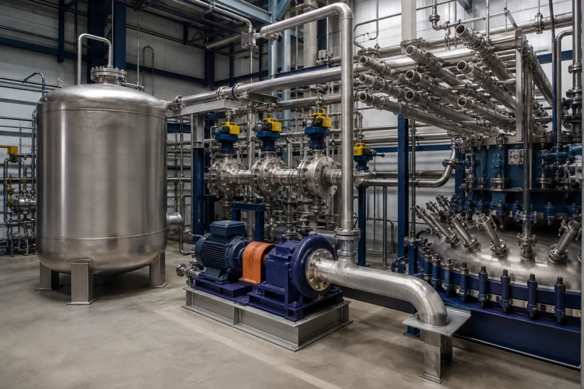
Emergency quench system for ammonium nitrate solution: flooding, tempering and pump trips that pull hot AN back from decomposition
Safety system for hot ammonium nitrate solution and melt · flood-on-high-temperature, a pump trip below the boiling point, and the temperature gaps between 130 °C storage, 180–195 °C neutralizers and 260 °C decomposition
A plant making ammonium nitrate holds tonnes of hot, concentrated solution in a neutralizer, a rundown tank and a storage tank. If that solution turns acidic, picks up chlorides or sits without flow, it can heat itself toward decomposition. The emergency quench system is the last active barrier: a reservoir of water, a pump and fast-opening valves that flood or temper the vessel when a temperature limit is crossed, together with trips that stop pumps before they heat a trapped charge. This page sets out the temperatures that define its trip points, what a published HAZOP asked it to do, and the conditions it cannot correct.
Emergency quench, flooding and tempering systems that cool and dilute hot ammonium nitrate solution or melt in neutralizers, rundown tanks, buffer tanks and liquid AN storage tanks, with their high-temperature trips and the pump interlocks in the AN transfer loops. The neutralisers and evaporators that make AN solution and melt, and their reactor choice, are covered on the Ammonium nitrate melt production and concentration system page; this page deals only with the emergency cooling and dilution added to them. Quench tanks for hardening steel parts in oil, polymer or water are covered on the Quench tank page, and PAG polymer quenchant systems on the Polymer quenching tank page. Fire-fighting water for stored solid AN, explosives formulation and the AN product itself are outside this page.
CNFX editorial research · Sources checked October 12, 2026 · 4 sources
From 130 °C storage to 260 °C decomposition: the temperature band an AN quench trip sits in
A quench trip has to sit above the hottest normal operating point and far enough below decomposition to stop it. The published figures for AN solution put those points closer together than the round numbers suggest, and the sources do not agree on where exothermic decomposition begins.
Editorial calculation: 267 °F is 130.6 °C, 392 °F is 200 °C and 446 °F is 230 °C. On these figures a conventional neutralizer at 180–195 °C runs 5–20 °C below EPA's approximate onset of exothermic decomposition, while the 260 °C figure for pure AN in the GE patent leaves 65–80 °C. Because the two sources differ by 60 °C on where the hazard begins, ask the system designer which decomposition temperature the trip settings were derived from and how sensitizers were allowed for.
The GE patent states that metal particles (aluminium in particular), wax, chlorinated materials and organics lower both the temperature and the pressure at which AN explodes, and that lime raises them. [4] EPA lists chromium, copper, silver, nickel, iron, palladium, gold, cerium and cobalt as metals that act with chlorides to lower decomposition temperatures further. [1]
Cooling too far is a hazard of its own: EPA notes that reduced temperatures can crystallise AN out of solution and that solid AN may be less difficult to initiate than 83% solution. [1] The Colombian HAZOP traces low tank temperature to a lost steam supply, leading to crystallised AN, blocked lines and lost production. [2]
Point
Published figure
Source
Liquid 83% AN held in a storage tank
130–150 °C, about 800 t in the tank studied (85% of capacity)
Give the supplier the normal and maximum operating temperature of each vessel, the AN concentration and the decomposition temperature your hazard study adopted; ask for the trip setting, alarm setting and the margin between them in writing.
02
Flooding the tank on high temperature and a SIL 3 tempering function: what a liquid-AN storage HAZOP asked for
Benedetti-Marquez and co-authors ran a HAZOP on a liquid AN storage tank at a petrochemical plant in the Caribbean region of Colombia, analysing 32 deviations of which 18 applied to that node. [2] Two of its recommendations describe the quench function directly.
For high temperature caused by excess steam to the tank coil after a temperature-indicator failure, the study recommends installing a tempering system, implementing a safety instrumented function at SIL 3 and checking the coil inspection plan. For low pH caused by feed from another tank, it recommends safety instruments or devices that flood the tank when high temperature is detected. [2]
The tank layout the study takes from EFMA (2005) already carries a vent for decomposition gases and for steam from added water, an overflow point, a steam coil to evaporate added water and hold temperature and concentration, a recirculation and discharge line and an ammonia addition line for pH. Its instruments are high and low level alarms, a high temperature switch, a low level switch, high and low temperature alarms, and low flow and pH alarms on the recirculation line. [2]
Water added in an emergency has to leave somewhere. The same HAZOP lists flood water entering the tank among the causes of high level, with AN spills, environmental impact and possible harm to people as consequences, and recommends that level transmitter and high-level switch signals go to different I/O cards. [2] Editorial note: the vent, the overflow point and the dike therefore form part of the quench design, not only the reservoir and pump.
Flood the vessel, not a stagnant pocket of it. In the Port Neal explosion, EPA found that lack of flow in the neutralizer and toward the rundown tank isolated the sensors needed to monitor the AN solution and let thermal and contaminant stratification develop without warning to the operator, a condition that lasted 15 hours before the explosion. [1] Editorial note: a quench triggered by a single temperature element can only act on what that element sees; ask where the elements sit relative to dead zones and how many vote.
State the vessel volume and AN inventory, the quench medium and its temperature, the required time to reach a safe temperature, the target SIL, how many temperature elements trip the system and the overflow, vent and containment that receive the added water.
03
A one-shot thermal fuse on the pump casing: stopping a dead-headed AN pump at 75 °C
Pumps in AN service can create the heat, concentration and confinement that decomposition needs on their own. GE's patent US5335577A, filed in 1993, describes a trip mounted on the pump itself. [4]
The patent explains that a partly blocked centrifugal pump heats its contents through friction, evaporates water so the AN concentrates, and confines the charge; a partly blocked discharge is enough to create the hazard. The conventional interlock is a thermocouple or resistance element in nearby piping, wired through a transmitter to a control system, which needs periodic calibration and testing. [4]
Its alternative is a fusible pellet holding a spring against an electrical contact in the motor control circuit, screwed into a pipe coupling welded to the pump casing at a point splashed by the rotating liquid. When the pellet melts, the contact opens, the pump stops and it stays off until the fuse is replaced, which forces an investigation before restart. The patent states that a 20 °C difference "will usually occur" between the pumped liquid and the fuse element, and in its example the fuse is designed to melt at 75 °C so that the liquid does not boil. A thermocouple or bimetallic switch on the casing are named as alternatives. [4]
The Colombian HAZOP reaches a similar point for the tank outlet pumps: low level can cause cavitation, heating or decomposition, and it recommends tripping the suction pump on low amperage or vibration, high temperature, or low or high discharge pressure. [2]
List every pump that can hold AN solution against a closed or blocked line, and agree whether each carries a casing temperature trip, a discharge-pressure trip or both.
04
Acid, chlorides and inventory: conditions a quench system cannot correct
EPA found that free acid is a significant source of or contributing factor to AN solution decomposition, and that stability falls as the solution becomes more acidic. At Port Neal the pH probe in the rundown line had been malfunctioning, chlorides were present, and the nitric acid had not been analysed for chloride since 1980. Action levels for chloride in the safety literature EPA reviewed range from 1 to 80 ppm by volume. [1]
EPA also records that violent decomposition of AN solutions has been documented at concentrations as low as 80% by weight in water. [1] Editorial note: diluting an 83% solution to just under 80% does not by itself take it out of the range EPA describes; the quench design basis has to state the target concentration and temperature together.
The amount of hot AN to be quenched depends on the process. Grande Paroisse gives up to 15 m³, or 21 t of ANS, in the reaction zone of a conventional neutralizer for a 1,200 t/d plant, against a pipe-reactor volume below 0.2 m³ and a separator holding around 2 m³ of ANS for a 2,000 t/d plant; it adds that pipe-reactor shutdown is immediate because there is no vessel to be emptied. [3] Editorial calculation: 21 t in 15 m³ is a solution density of 1.4 t/m³, and the separator inventory per tonne of daily capacity is about one-twelfth of the conventional neutralizer's (0.001 m³ per t/d against 0.0125 m³ per t/d).
Ask for the pH and chloride monitoring on the feeds, the inventory of each vessel the quench serves and the procedure for a vessel left charged without flow.
05
What to send for an AN emergency quench system
Paste it into your enquiry below or into an email to a maker, then replace every bracket.
Vessels: [neutralizer / rundown / buffer / storage; volume; AN inventory]
Solution: [AN concentration; normal and maximum temperature; pH range]
Design basis: [decomposition temperature adopted; target temperature and concentration after quench]
Trip: [temperature elements; voting; alarm and trip settings; target SIL]
Quench: [medium; reservoir volume; flow; time to safe state]
Disposal: [vent; overflow; dike or catch tank]
Pumps: [AN pumps needing casing or discharge trips]
Explore company information and manufacturing capabilities, then discuss the scope of your project with a relevant supplier.
Share this page
Compiled and source-reviewed by the CNFX editorial team.
Each manufacturer above links to the page on that company's own website where the product is listed, with the date we checked it. How we source and review
· Page last updated 13 October 2026
Buyer questions
At what temperature does ammonium nitrate solution begin to decompose?
EPA's Port Neal report gives approximately 392 °F (200 °C) for rapid exothermic decomposition to N₂O and water, while GE's patent gives 260 °C and 1,422 psi for pure AN and the AIDIC study 260–290 °C for side reactions on rapid heating. Sensitizers such as chlorides and some metals lower these temperatures. [1][4][2]
What does an emergency quench do in an AN storage tank?
A HAZOP of a liquid AN storage tank held at 130–150 °C recommended a tempering system at SIL 3 for high temperature and devices that flood the tank when high temperature is detected. [2]
Why does pump protection matter in AN service?
A partly blocked centrifugal pump can heat, concentrate and confine AN. GE's patent puts a one-shot thermal fuse on the pump casing that stops the pump; in its example the fuse melts at 75 °C. [4]
How much AN might a quench system have to deal with?
Grande Paroisse gives up to 15 m³ (21 t) of solution in a conventional neutralizer for a 1,200 t/d plant, and about 2 m³ in the separator of a 2,000 t/d pipe-reactor plant. [3]
Sources and what still needs a direct check
Sources checked 2026-10-12. Decomposition temperatures, sensitizers, pH, chloride action levels and the no-flow finding come from EPA Region 7's investigation of the Port Neal explosion; storage temperature, tank layout and the flooding and SIL 3 recommendations from a HAZOP published in Chemical Engineering Transactions; neutralizer temperatures and inventories from a Grande Paroisse paper to the 2004 IFA Technical Conference; the pump trip from GE's patent US5335577A.