Editorial Technical Reference

Flow Cell

This page explains how Flow Cell is classified within Chemical Manufacturing. Technical values and manufacturer relationships are research references; confirm the current specification and supplier evidence for each order.

Technical Definition & Core Assembly

A transparent chamber or cuvette designed to hold liquid samples for optical analysis within analytical instruments.
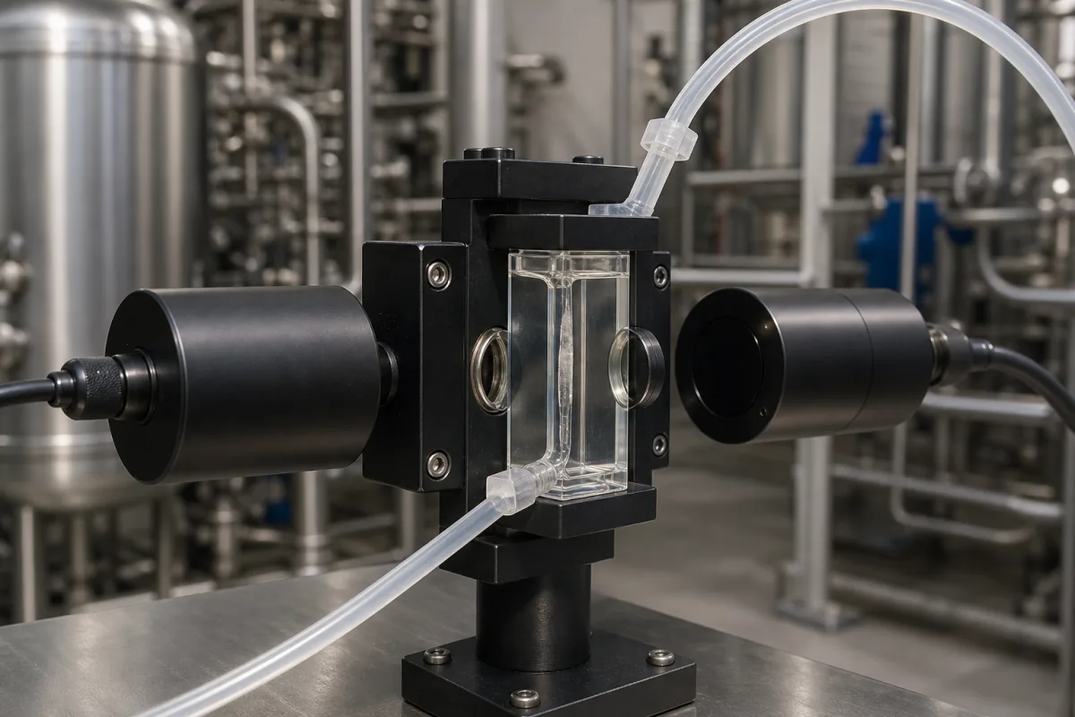
Representative product image. Confirm appearance and specifications with the manufacturer.

Product Specifications

Technical details and manufacturing context for Flow Cell

Definition
A flow cell is a critical component of Process Analytical Technology (PAT) modules that provides a controlled environment for liquid samples to pass through while being analyzed by optical sensors. It serves as the interface between the process stream and analytical instrumentation, enabling real-time monitoring of chemical, biological, or physical properties during manufacturing processes. The flow cell is designed to maintain a consistent optical path length and minimize sample disturbance, ensuring accurate and reproducible measurements. It is typically constructed from materials such as optical-grade quartz, sapphire, stainless steel 316L, PTFE, or borosilicate glass, selected for chemical compatibility and optical clarity. Key parameters include optical path length (1–100 mm), cell volume (1–100 µL), operating pressure (1.0–1.6 MPa), and operating temperature (10–50 °C). Wetted materials may include PEEK, PTFE, fused silica, or stainless steel 316, while window materials are often UV-grade fused silica or sapphire. Path length tolerance is ±0.05 mm, and connection threads are typically 10–32 UNF or 1/4-28 UNF. Leak rate is specified as ≤1×10⁻⁹ Pa·m³/s per ISO 20485, and chemical resistance covers pH 1–14. Weight ranges from 50–200 g. These values are reference ranges; actual specifications must be confirmed with the manufacturer for the specific model and application. The flow cell is essential for real-time process monitoring, enabling quality control and optimization in chemical manufacturing.
Working Principle
Liquid samples are pumped through the flow cell's chamber, which has precisely aligned optical windows. Light sources (UV, visible, IR, etc.) pass through the sample, and detectors measure absorbance, fluorescence, or scattering properties. The flow cell maintains consistent pathlength and minimizes sample disturbance to ensure accurate, reproducible measurements. The optical path length and cell volume are selected based on the sensitivity required and sample availability. Operating pressure and temperature must be within specified limits to prevent leakage or optical distortion. The wetted materials and window material must be chemically compatible with the sample to ensure integrity. Regular verification of path length tolerance and leak rate is recommended to maintain performance.
Common Materials
Optical-grade quartz, Sapphire, Stainless steel 316L, PTFE (Teflon), Borosilicate glass
Technical Parameters
ParameterTypical rangeNotes & selection driver
Optical Path Length1–100 mmDetermines sensitivity; longer path for low concentrations.
Cell Volume1–100 µLSmaller volume reduces sample consumption.
Operating Temperature10–50 °CExceeding range may cause leakage or optical distortion.
Wetted MaterialsPEEK, PTFE, fused silica, stainless steel 316Chemical compatibility critical for sample integrity.
Window MaterialUV-grade fused silica, sapphireUV-grade for 190 nm; sapphire for high pressure.
Path Length Tolerance±0.05 mmEnsures measurement reproducibility.
Connection Thread10–32 UNF, 1/4-28 UNFStandard fittings for leak-free connections.
Leak Rate≤1×10⁻⁹ Pa·m³/sHelium leak test; ensures no sample loss.ISO 20485
Chemical ResistancepH 1–14Resistant to most solvents and acids/bases.
Weight50–200 gAffects handling and mounting.

Ranges are indicative industry figures for RFQ preparation, not a supplier commitment. Confirm every value and standard with the legal manufacturer before ordering.

Components / BOM
  • Optical Windows Part
    Allow light transmission into and out of the sample chamber
    Material: Quartz or sapphire
  • Sample Chamber
    Holds liquid sample during analysis
    Material: Stainless steel or PTFE
  • Inlet/Outlet Ports Part
    Connect to fluid delivery system for sample introduction and removal
    Material: Stainless steel
  • Seals/Gaskets Part
    Prevent leaks and maintain pressure integrity
    Material: Viton, Kalrez, or PTFE

Applied To / Applications

This component is essential for the following industrial systems and equipment:

Industrial Ecosystem & Supply Chain Structure

Complementary Systems
Downstream Applications
Specialized Tooling

Application Fit & Sizing Matrix

Operational Limits
pressure: 0 to 5 bar
flow rate: 0.1 to 10 mL/min
temperature: -10°C to 80°C
slurry concentration: Up to 20% solids by weight
Media Compatibility
✓ Aqueous solutions ✓ Organic solvents (e.g., ethanol, acetone) ✓ Biological buffers (e.g., PBS, Tris)
Unsuitable: Concentrated acids (e.g., >10% HCl) or bases (e.g., >5M NaOH)
Sizing Data Required
  • Sample volume (mL)
  • Optical path length (mm)
  • Required flow rate (mL/min)

Reliability & Engineering Risk Analysis

Failure Mode & Root Cause
Cavitation
Cause: Pressure drop below vapor pressure in high-velocity areas, causing vapor bubble formation and implosion that erodes internal surfaces
Corrosion fatigue cracking
Cause: Combined effect of cyclic stresses from flow-induced vibrations and corrosive fluid attack, leading to crack initiation and propagation in wetted components
Maintenance Indicators
  • Unusual high-frequency vibration or audible 'crackling' noise indicating cavitation
  • Visible external leaks or weeping at seals/connections, or abnormal pressure drop across the cell
Engineering Tips
  • Maintain fluid velocity within design limits and ensure proper inlet/outlet piping configuration to minimize turbulence and pressure fluctuations
  • Implement regular ultrasonic thickness testing and vibration monitoring to detect early-stage wall thinning and structural degradation

Indicative industry ranges for design and RFQ preparation. Confirm the exact figures and applicable standard with the manufacturer before specifying.

Compliance & Manufacturing Standards

Applicable Standards
ISO 10933:2018 (Laboratory glassware - Flow cells) ASTM E275-08 (Standard Practice for Describing and Measuring Performance of Ultraviolet, Visible, and Near-Infrared Spectrophotometers) CE Marking (EU compliance for safety and performance)

Quoted from the published standard.

Manufacturing Precision
  • Optical path length: +/-0.01mm
  • Window parallelism: <0.1 mrad
Quality Inspection
  • Leak test (pressure or vacuum method)
  • Optical transmission/absorbance verification

Manufacturers of Flow Cell

Manufacturer profiles associated with Flow Cell.

Sourcing Flow Cell from China?
Tell us your specification and target quantity — we will match it against manufacturer records and come back with the factories that fit.
Request manufacturers We manufacture this

Manufacturer listings support early research and capability understanding. They are not certification, ranking, or transaction guarantees.

Technical documentation
Request current drawings, revision history, and a signed specification sheet.
Manufacturing capability
Verify equipment lists, process limits, capacity, and representative production evidence.
Inspection readiness
Confirm test methods, calibrated equipment, sampling plans, and traceable reports.
Supplier transparency
Check the legal entity, factory address, ownership, certifications, and direct contacts.

CNFX does not score or rank suppliers. Buyers must verify all claims and documents with the legal manufacturer before ordering.

Supply Chain Compatible Machinery & Devices

Automated pH Monitoring and Dosing System

Automated system for continuous pH monitoring and chemical dosing in process streams.

Explore Specs →
Automated Powder Dispensing and Blending System

Automated system for precise dispensing and homogeneous blending of powdered chemicals.

Explore Specs →
Automated Viscosity Control and Mixing System

The Automated Viscosity Control and Mixing System is an industrial automation solution designed for continuous monitoring and adjustment of viscosity in chemical mixing and blending operations.

Explore Specs →
Automated Catalyst Loading and Unloading System

The Automated Catalyst Loading and Unloading System is an integrated automation solution for the precise and safe transfer of catalyst materials in fixed-bed reactors, continuous stirred-tank reactors, and other catalytic process vessels.

Explore Specs →

Frequently Asked Questions

What is the typical optical path length range for a flow cell?

The optical path length typically ranges from 1 to 100 mm, depending on the sensitivity required. Longer paths are used for low concentrations, while shorter paths are for higher concentrations. The exact value must be confirmed for the specific model.

What materials are commonly used for flow cell construction?

Common materials include optical-grade quartz, sapphire, stainless steel 316L, PTFE, and borosilicate glass. Wetted materials may include PEEK, PTFE, fused silica, or stainless steel 316. Window materials are often UV-grade fused silica or sapphire. Material selection depends on chemical compatibility and optical requirements.

What are the operating pressure and temperature limits?

The operating pressure is typically 1.0 to 1.6 MPa, and the operating temperature is 10 to 50 °C. Exceeding these ranges may cause leakage or optical distortion. Always verify the limits for the specific model.

How is the leak rate specified and verified?

The leak rate is specified as ≤1×10⁻⁹ Pa·m³/s, per ISO 20485. This is verified through helium leak testing to ensure no sample loss. Regular verification is recommended to maintain measurement integrity.

Data Basis

Editorial classification, named public sources where available, and source-reviewed manufacturer records.

Preliminary Technical Classification
This page supports structured research, RFQ preparation, and supplier evaluation. It does not replace buyer-led supplier qualification, standards review, or technical approval.
Buyer enquiry

Request manufacturing insight for Flow Cell

Ask for use case, specification boundaries, supplier type, and RFQ preparation information for this product.

Where it goes
Straight to the CNFX editorial desk, and to the manufacturer if this product is linked to a claimed profile. Nothing is broadcast to a supplier list.
Your details stay here
We do not sell or rent enquiry data, and we do not add you to a mailing list. Used only to answer this request.
No commission, no middleman
CNFX is a directory. We take no cut of any order and never negotiate on a supplier's behalf.
What we don't claim
A listing is not an endorsement. Qualify every supplier and verify every figure yourself before ordering.

Your business information is used only to process this request.

Thank you! Your message has been sent. We'll respond within 1–3 business days.
Sorry, we couldn't send your message. Please try again, or email us at contact@cnfx.com.

Need to Manufacture Flow Cell?

Compare manufacturer profiles with relevant product and process capability.

Previous Product
Emulsifier Dosing System
Next Product
Fractionating Column
Get QuotesChat