Editorial Technical Reference

Flow Control Valve (per branch)

This page explains how Flow Control Valve (per branch) is classified within Chemical Manufacturing. Technical values and manufacturer relationships are research references; confirm the current specification and supplier evidence for each order.

Technical Definition & Core Assembly

A valve designed to regulate and control the flow rate of urea melt in individual distribution branches within a urea melt distribution system.
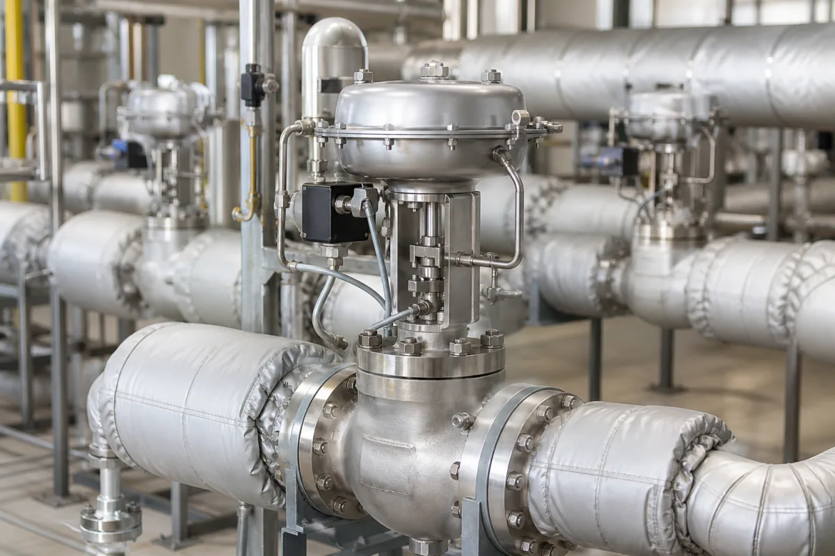
Representative product image. Confirm appearance and specifications with the manufacturer.

Product Specifications

Technical details and manufacturing context for Flow Control Valve (per branch)

Definition
This flow control valve is a specialized component used in urea melt distribution systems within chemical manufacturing plants. Its primary function is to precisely regulate the flow rate of urea melt to individual branches or distribution lines, ensuring consistent and accurate delivery to downstream processes. By maintaining optimal flow balance, the valve prevents flow imbalances between different branches, which is critical for process stability and product quality.

The valve operates by adjusting the flow area through a movable element such as a plug, ball, or gate, which is controlled by an actuator. As the actuator position changes, the flow passage constricts or expands, thereby regulating the flow rate. This adjustment can be manual or automated based on system requirements.

Key parameters for selection include nominal diameter (DN15–DN50, ISO 6708), operating pressure (1.0–1.6 MPa), operating temperature (130–150°C, as urea melt solidifies below 130°C), flow coefficient (Kv 2.5–25, IEC 60534-2-3), flow control accuracy (±2%), leakage rate (≤0.01% of max flow, ISO 5208 Class VI), actuator type (pneumatic), supply pressure (0.4–0.6 MPa, ISO 6358), electrical signal (4–20 mA, IEC 60381-1), body material (316L, ASTM A351 CF3M), seat material (Stellite 6, ASTM A608), connection type (flanged, ASME B16.5), and weight (15–60 kg).

Materials on file include stainless steel (316L/304) and alloy steel. These values are reference ranges and must be verified for the specific model and application with the legal manufacturer or supplier. The valve is designed for easy maintenance with flanged connections. It is essential to confirm that the selected valve meets the required standards and performance criteria for your specific urea melt distribution system.
Working Principle
The valve regulates flow by adjusting the flow area through a movable element (plug, ball, or gate) controlled by an actuator. As the actuator moves, the flow passage changes, increasing or decreasing the flow rate. Manual or automated adjustment is possible. The valve maintains precise flow control to ensure uniform distribution across branches, preventing imbalances. The actuator is typically pneumatic, requiring a supply pressure of 0.4–0.6 MPa, and may receive a 4–20 mA signal for positioner feedback. The valve is designed to operate within specified pressure and temperature ranges, and its leakage rate is minimal to prevent cross-contamination.
Common Materials
Stainless Steel (316L/304), Alloy Steel
Technical Parameters
ParameterTypical rangeNotes & selection driver
Nominal DiameterDN15–DN50 mmMatch branch pipe sizeISO 6708
Operating Pressure1.0–1.6 MPaBelow 1.0 MPa seat load insufficient
Operating Temperature130–150 °CUrea melt solidifies below 130°C
Flow Coefficient2.5–25 KvSelect for required flow rangeIEC 60534-2-3
Flow Control Accuracy±2 %Maintains uniform distribution
Leakage Rate≤0.01 % of max flowPrevents cross-contaminationISO 5208 Class VI
Actuator TypePneumaticFor remote control
Supply Pressure0.4–0.6 MPaFor pneumatic actuatorISO 6358
Electrical Signal4–20 mAFor positioner feedbackIEC 60381-1
Body Material316LCorrosion resistant to urea meltASTM A351 CF3M
Seat MaterialStellite 6Wear resistant at high tempASTM A608
Connection TypeFlangedFor easy maintenanceASME B16.5
Weight15–60 kgDepends on size and actuator

Ranges are indicative industry figures for RFQ preparation, not a supplier commitment. Confirm every value and standard with the legal manufacturer before ordering.

Components / BOM
  • Valve Body
    Main pressure-containing structure that houses internal components and connects to piping.
    Material: Stainless Steel
  • Trim (Seat & Plug/Disc) Part
    Internal components that directly regulate flow by adjusting the orifice area; provides sealing.
    Material: Stainless Steel / Hardened Alloy
  • Stem Part
    Connects the actuator to the trim, transmitting motion to open or close the valve.
    Material: Stainless Steel
  • Actuator
    Provides the force to position the valve stem and trim, controlling flow.
    Material: Aluminum / Steel / Composite
  • Packing / Seals Part
    Prevents leakage along the stem where it exits the valve body.
    Material: Graphite / PTFE / Elastomer

Industry Taxonomies & Aliases

Commonly used trade names and technical identifiers for Flow Control Valve (per branch).

Applied To / Applications

This component is essential for the following industrial systems and equipment:

Industrial Ecosystem & Supply Chain Structure

Complementary Systems
Downstream Applications
Specialized Tooling

Application Fit & Sizing Matrix

Operational Limits
pressure: Up to 25 bar
flow rate: 0.5 to 50 L/min per branch
temperature: -20°C to 200°C
slurry concentration: Up to 70% urea melt by weight
Media Compatibility
✓ Urea melt (ammonium carbamate solution) ✓ Aqueous ammonia solutions ✓ Process water with low solids content
Unsuitable: Chloride-containing media or environments with high chloride contamination
Sizing Data Required
  • Required flow rate (L/min)
  • System pressure differential (bar)
  • Urea melt concentration (% by weight)

Reliability & Engineering Risk Analysis

Failure Mode & Root Cause
Cavitation
Cause: Pressure drop below vapor pressure causing bubble formation and implosion, damaging valve trim and body surfaces due to localized high-pressure shock waves.
Sticking or binding
Cause: Accumulation of process media deposits, corrosion products, or foreign particles on valve stem, seat, or guiding surfaces, often exacerbated by improper material selection or inadequate maintenance.
Maintenance Indicators
  • Audible hissing or whistling indicating internal leakage past the valve seat
  • Visible external leakage around stem packing or body flanges, often accompanied by process fluid stains or drips
Engineering Tips
  • Implement regular valve stroking exercises during normal operation to prevent deposit buildup and verify full range of motion, especially for valves in infrequent service.
  • Install upstream strainers or filters to protect valve internals from particulate contamination, and specify appropriate trim materials (e.g., hardened alloys) for abrasive or corrosive service conditions.

Indicative industry ranges for design and RFQ preparation. Confirm the exact figures and applicable standard with the manufacturer before specifying.

Compliance & Manufacturing Standards

Applicable Standards
ISO 5208:2015 (Industrial valves - Pressure testing of valves) ANSI/FCI 70-2 (Control Valve Seat Leakage) DIN EN 12516-1 (Industrial valves - Shell design strength)

Quoted from the published standard.

Manufacturing Precision
  • Bore diameter: +/-0.02mm
  • Seat flatness: 0.05mm maximum deviation
Quality Inspection
  • Hydrostatic shell test (1.5x rated pressure)
  • Flow coefficient (Cv) verification test

Manufacturers of Flow Control Valve (per branch)

Manufacturer profiles associated with Flow Control Valve (per branch).

Sourcing Flow Control Valve (per branch) from China?
Tell us your specification and target quantity — we will match it against manufacturer records and come back with the factories that fit.
Request manufacturers We manufacture this

Manufacturer listings support early research and capability understanding. They are not certification, ranking, or transaction guarantees.

Technical documentation
Request current drawings, revision history, and a signed specification sheet.
Manufacturing capability
Verify equipment lists, process limits, capacity, and representative production evidence.
Inspection readiness
Confirm test methods, calibrated equipment, sampling plans, and traceable reports.
Supplier transparency
Check the legal entity, factory address, ownership, certifications, and direct contacts.

CNFX does not score or rank suppliers. Buyers must verify all claims and documents with the legal manufacturer before ordering.

Supply Chain Compatible Machinery & Devices

Continuous Flow Reactor System

A modular, automated chemical processing system designed for continuous flow synthesis of chemical products.

Explore Specs →
Automated Batch Crystallization System

Automated system for controlled crystallization of chemical compounds in batch processes.

Explore Specs →
Automated pH Monitoring and Dosing System

Automated system for continuous pH monitoring and chemical dosing in process streams.

Explore Specs →
Automated Powder Dispensing and Blending System

Automated system for precise dispensing and homogeneous blending of powdered chemicals.

Explore Specs →

Frequently Asked Questions

What is the purpose of this flow control valve?

It regulates the flow rate of urea melt to individual branches in a distribution system, ensuring consistent delivery and preventing flow imbalances.

What are the key parameters to consider when selecting this valve?

Nominal diameter, operating pressure and temperature, flow coefficient, flow control accuracy, leakage rate, actuator type, supply pressure, electrical signal, body and seat materials, connection type, and weight. These must be verified for your specific application.

What materials are available for this valve?

Stainless steel (316L/304) and alloy steel are listed as materials on file. The body material is typically 316L, and the seat material is Stellite 6, but confirm with the manufacturer.

How is the valve actuated?

The valve is typically actuated pneumatically, requiring a supply pressure of 0.4–0.6 MPa. It may also have a positioner with a 4–20 mA electrical signal for remote control.

Data Basis

Editorial classification, named public sources where available, and source-reviewed manufacturer records.

Preliminary Technical Classification
This page supports structured research, RFQ preparation, and supplier evaluation. It does not replace buyer-led supplier qualification, standards review, or technical approval.
Buyer enquiry

Request manufacturing insight for Flow Control Valve (per branch)

Ask for use case, specification boundaries, supplier type, and RFQ preparation information for this product.

Where it goes
Straight to the CNFX editorial desk, and to the manufacturer if this product is linked to a claimed profile. Nothing is broadcast to a supplier list.
Your details stay here
We do not sell or rent enquiry data, and we do not add you to a mailing list. Used only to answer this request.
No commission, no middleman
CNFX is a directory. We take no cut of any order and never negotiate on a supplier's behalf.
What we don't claim
A listing is not an endorsement. Qualify every supplier and verify every figure yourself before ordering.

Your business information is used only to process this request.

Thank you! Your message has been sent. We'll respond within 1–3 business days.
Sorry, we couldn't send your message. Please try again, or email us at contact@cnfx.com.

Need to Manufacture Flow Control Valve (per branch)?

Compare manufacturer profiles with relevant product and process capability.

Previous Product
Twin-Screw Polymer Compounding Extruder
Last Product
Get QuotesChat