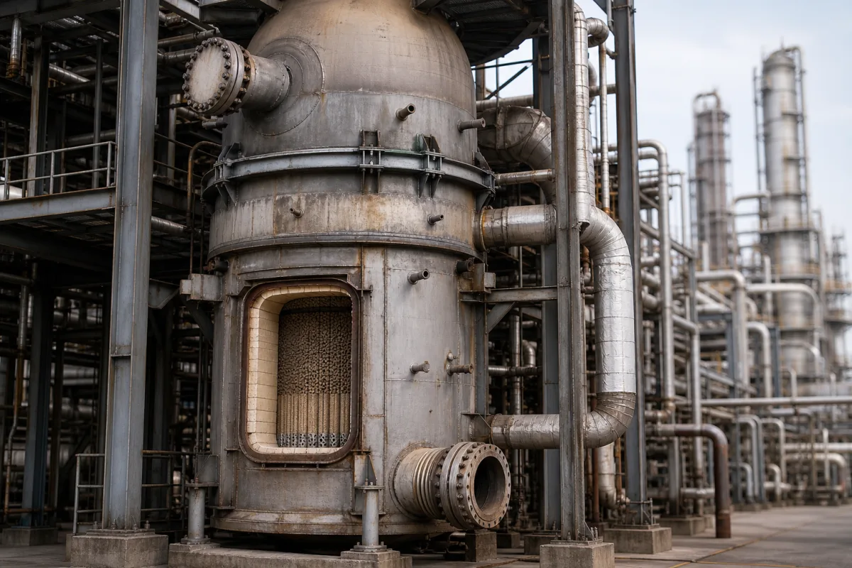
Reformer reactor (steam methane and autothermal reformers)
Steam methane, secondary and autothermal reformer reactors for syngas and hydrogen · Fired tubular reformers versus refractory-lined autothermal vessels, outlet temperature and methane slip, burner mixing, catalyst bed and hold-down, alumina vaporisation, pressure range and inspection downtime
A reformer reactor converts natural gas or another hydrocarbon with steam — and, in autothermal designs, oxygen or air — over a nickel catalyst into synthesis gas of hydrogen, carbon monoxide and carbon dioxide for hydrogen, ammonia or methanol plants. It comes in two main forms: a fired tubular steam reformer, where catalyst-filled tubes are heated from outside, and a refractory-lined autothermal or secondary reformer vessel, where part of the gas is burnt inside the vessel above a fixed catalyst bed. Ask three things first: what product gas, flow and methane slip the plant needs, what pressure and outlet temperature the process runs at, and whether heat comes from furnace firing or internal combustion.
Reformer reactors for syngas and hydrogen: fired tubular steam methane reformers, refractory-lined secondary and autothermal reformer vessels with burners, catalyst beds and supports, and gas-heated reformer exchangers. Individual catalyst tubes (see catalyst tubes), catalytic reformers for refinery naphtha, small fuel-cell fuel processors, shift converters and pressure-swing adsorption units are outside this page except where compared.
CNFX editorial research · Sources checked October 11, 2026 · 4 sources
The U.S. Department of Energy describes steam methane reforming as a mature process in which high-temperature steam (700–1,000 °C) produces hydrogen from methane under 3–25 bar in the presence of a catalyst; the reaction is endothermic, so heat must be supplied, and a water-gas shift step and pressure-swing adsorption follow. It states that partial oxidation, by contrast, is exothermic, faster and needs a smaller reactor vessel, but initially yields less hydrogen per unit of fuel. [1]
Johnson Matthey's 2024 training seminar on autothermal and secondary reforming gives a steam (primary) reformer exit of 750–850 °C with 8–12% methane, followed by an autothermal or secondary reformer exiting at 950–1,050 °C with 0.3–0.5% methane. In ammonia plants the secondary reformer adds nitrogen through process air, raises heat for high-pressure steam and allows a smaller primary reformer; oxygen-fired autothermal reformers are used in hydrogen and methanol plants to cut primary reformer duty or take feeds such as coke oven gas. [2]
A 1991 M.W. Kellogg patent describes the conventional secondary reformer as a refractory-lined vessel filled with nickel-containing catalyst with no provision for external heat, the heat coming from burning part of the primary reformed gas with air; its own process runs an autothermal zone adiabatically at 22–70 bar to produce gas below 1.0% methane at 900–1,100 °C, and uses that hot gas to heat catalyst-filled bayonet tubes in a reactor/exchanger in place of part of the fired furnace. [3]
Topsoe's patent application US 2023/0271829 A1 for an ATR-based hydrogen plant with no steam methane reformer states that SMR-based plants operate at a steam-to-carbon ratio of about 3, whereas its ATR runs at a molar steam-to-carbon ratio of 0.4 or higher but not above 2.0, at 20–30 barg (for instance 24–28 barg), below the 30–40 barg it gives for conventional ATR operation. It puts synthesis gas at the ATR exit between 900 and 1,100 °C, with 1,000–1,075 °C as the preferred band, and in its worked description the gas leaves at about 1,050 °C through a refractory-lined outlet section and transfer line to waste heat boilers; the application targets capture of 95% or more of the feed carbon. [4] Editorial note: the steam-to-carbon ratio sets the steam load on the vessel and its shift train, so fix it with the licensor before sizing the reactor and its outlet line.
Give the supplier the plant product (hydrogen, ammonia or methanol syngas), feed gas analysis and flow, steam-to-carbon ratio, oxidant (air, enriched air or oxygen), operating pressure, required outlet temperature and methane slip, whether a fired primary reformer exists or is to be replaced, downstream waste heat recovery, and turndown.
02
Specify the vessel, burner and catalyst bed
Johnson Matthey lists the mechanical features of an autothermal or secondary reformer as a refractory-lined pressure shell, water jackets to keep the shell cool, a combustion section in the upper region and a fixed catalyst bed in the lower region supported on a refractory brick arch, loaded with alumina hold-down lumps or target tiles, a guard layer and the main catalyst bed. It gives an air or oxygen inlet at 200–250 °C, process gas inlet at 650–750 °C, 1,000–1,300 °C in the combustion zone and reformed gas outlet at 950–1,050 °C. [2]
The burner combusts only about 20% of the process gas and must mix in the other 80% uniformly; poor mixing from burner design, installation, insufficient mixing volume or burner gun failure raises the approach to equilibrium and methane slip. Oxygen firing gives higher flame temperatures, needs higher alloys for burners, makes the refractory duty more arduous and can vaporise alumina, which then recrystallises on cooler catalyst, raising pressure drop, binding catalyst, maldistributing gas and fouling the downstream boiler. Nickel sintering is named as the main catalyst deactivation mechanism, and catalyst can break up after plant upsets such as wetting. [2]
Johnson Matthey puts the value of reducing methane slip by 0.1% in a 2,000 t/d ammonia plant at about 14 t/d of ammonia with hydrogen recovery and over 30 t/d without, and estimates that skimming a fouled bed takes about 30 hours to shut down and purge, 3 days to enter, clear, inspect and recharge, and 30 hours to restart. In one case a new burner and catalyst cut secondary reformer methane slip from 0.36 to 0.25 mol%, allowing 15 t/d more production valued at US$820,000 a year. [2]
Editorial calculation: 15 t/d × US$150/t margin (the margin stated in the same case) × 365 days ≈ US$821,000 a year, consistent with the figure given; the downtime estimate above adds up to about 5.5 days of lost production per bed skim. [2]
Ask for the shell design pressure and temperature, refractory system and thicknesses with hot-face and shell temperature calculations, water jacket or shell cooling design, burner type and material, mixing volume, catalyst and hold-down loading plan, bed support design, guaranteed outlet temperature, methane slip, approach to equilibrium and pressure drop, and start-up, ignition and trip philosophy.
03
Tubular, air-fired, oxygen-fired and gas-heated reformers side by side
Adds nitrogen for ammonia; 0.3–0.5% CH4 exit. [2][3]
Air rate, burner, bed.
Oxygen-fired autothermal reformer
Hydrogen and methanol plants; harsher refractory duty. [2] One hydrogen design: S/C 0.4–2.0, 20–30 barg, exit about 1,050 °C. [4]
Burner alloy, alumina vaporisation.
Gas-heated reactor/exchanger
Bayonet catalyst tubes heated by reformed gas, 22–70 bar. [3]
Tube design, heat balance.
04
A hydrogen-unit builder that lists the reformer furnace
Sichuan Ally lists natural-gas hydrogen production units with the reformer furnace as the core equipment; ask it which licensor's design and which pressure-vessel code it builds to.
05
Shell, refractory, burner, hold-down and bed support
Read the burner row closely: Johnson Matthey links poor mixing to higher methane slip, and oxygen firing to higher burner alloys and harder refractory duty. [2]
Explore company information and manufacturing capabilities, then discuss the scope of your project with a relevant supplier.
Share this page
Compiled and source-reviewed by the CNFX editorial team.
Each manufacturer above links to the page on that company's own website where the product is listed, with the date we checked it. How we source and review
· Page last updated 13 October 2026
Buyer questions
What is the difference between a primary and a secondary reformer?
The primary reformer heats catalyst tubes from outside and exits at 750–850 °C with 8–12% methane; the secondary burns part of the gas inside a refractory-lined vessel and exits at 950–1,050 °C with 0.3–0.5% methane. [2]
At what pressure does steam methane reforming run?
DOE gives 3–25 bar, with steam at 700–1,000 °C over a catalyst. [1]
Why does burner mixing matter in an autothermal reformer?
The burner combusts about 20% of the gas and must mix in the rest; poor mixing raises methane slip and costs production. [2]
What steam-to-carbon ratio does an autothermal reformer run at?
Topsoe's US 2023/0271829 A1 gives about 3 for SMR-based plants and 0.4 to 2.0 for its ATR, at 20–30 barg with exit gas at about 1,050 °C. [4]
Sources and what still needs a direct check
Sources checked 2026-10-11. DOE gives a public overview; Johnson Matthey's seminar slides present one catalyst and burner supplier's experience; the Kellogg patent describes one licensor's process, and the Topsoe patent application describes an ATR-only hydrogen plant. Guarantees for your reactor must come from the licensor and fabricator offered.