Editorial Technical Reference

Analog/Digital Converter

This page explains how Analog/Digital Converter is classified within Computer, Electronic and Optical Product Manufacturing. Technical values and manufacturer relationships are research references; confirm the current specification and supplier evidence for each order.

Technical Definition & Core Assembly

Electronic device that converts continuous analog signals into discrete digital values for processing by digital systems.

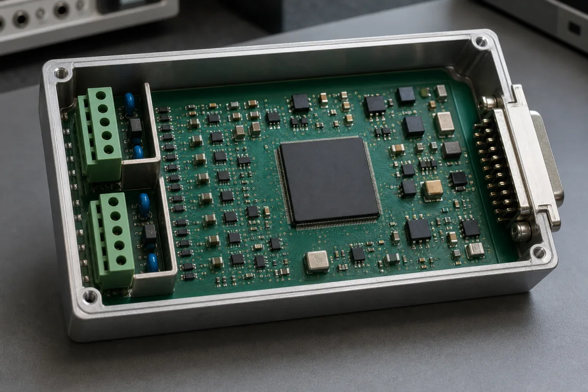
Representative product image. Confirm appearance and specifications with the manufacturer.

Product Specifications

Technical details and manufacturing context for Analog/Digital Converter

Definition
An analog-to-digital converter (ADC) is a component used in process controllers and other electronic systems to translate real-world analog signals—such as temperature, pressure, or flow measurements—into digital data that digital logic and algorithms can process. The converter samples the continuous analog input at regular intervals, quantizes each sample to the nearest discrete level based on its resolution, and encodes these levels into binary output using techniques like successive approximation, delta-sigma modulation, or flash conversion. Typical specifications include a resolution of 8–24 bits, a sampling rate of 1–1000 kSPS, an input voltage range of 0–5 V (unipolar or bipolar), a supply voltage of 2.7–5.5 V DC, and power consumption of 0.5–100 mW. The signal-to-noise ratio ranges from 60–120 dB, integral nonlinearity from ±0.5 to ±4 LSB, and operating temperature from -40 to 85 °C. Input impedance is 10–1000 MΩ, and digital interfaces include SPI or I2C. Package types range from SOIC-8 to QFN-32, with a weight of 0.1–2 g. Common materials include semiconductor silicon, copper, and plastic encapsulation. These values are typical ranges; actual performance depends on the specific model and application. When selecting an ADC, verify the required resolution, sampling rate, input range, supply voltage, power budget, interface compatibility, and package constraints. Confirm model-specific parameters and standards with the legal manufacturer or supplier before procurement. The converter's role is critical in ensuring accurate digital representation of analog signals, affecting overall system precision and reliability.
Working Principle
The converter samples the continuous analog input signal at regular intervals, quantizes each sample to the nearest discrete level based on its resolution, and encodes these levels into binary digital output values using techniques such as successive approximation, delta-sigma modulation, or flash conversion. The sampling rate determines how often the signal is captured, while resolution defines the number of discrete levels. Higher resolution provides finer quantization but may trade off with sampling speed. The input voltage range must match the sensor output, and the supply voltage must be within the specified range. The digital output is transmitted via SPI or I2C to the controller. Power consumption is a key consideration for battery-powered devices. The converter's performance is characterized by signal-to-noise ratio, integral nonlinearity, and input impedance, which affect accuracy and signal integrity.
Common Materials
Semiconductor silicon, Copper, Plastic encapsulation
Technical Parameters
ParameterTypical rangeNotes & selection driver
Resolution8–24 bitHigher resolution for finer quantization
Sampling Rate1–1000 kSPSTrade-off with resolution
Input Voltage Range0–5 VUnipolar or bipolar options
Supply Voltage2.7–5.5 V DCSingle or dual supply
Power Consumption0.5–100 mWCritical for battery-powered devices
Signal-to-Noise Ratio60–120 dBHigher is better for accuracy
Integral Nonlinearity±0.5–±4 LSBDeviation from ideal transfer function
Operating Temperature-40–85 °CIndustrial grade range
Input Impedance10–1000 High impedance to avoid loading
Interface TypeSPI/I2CDigital output protocol
Package TypeSOIC-8–QFN-32Surface mount options
Weight0.1–2 gDepends on package

Ranges are indicative industry figures for RFQ preparation, not a supplier commitment. Confirm every value and standard with the legal manufacturer before ordering.

Components / BOM
  • Sample and Hold Circuit Part
    Captures and maintains the analog input voltage during conversion process
    Material: Semiconductor components
  • Quantizer
    Determines the digital value corresponding to the sampled analog level
    Material: Semiconductor logic circuits
  • Encoder
    Converts the quantized level into binary digital output code
    Material: Digital logic circuits
  • Reference Voltage Source
    Provides stable voltage reference for accurate conversion
    Material: Precision voltage regulator components

Industry Taxonomies & Aliases

Commonly used trade names and technical identifiers for Analog/Digital Converter.

Applied To / Applications

This component is essential for the following industrial systems and equipment:

Industrial Ecosystem & Supply Chain Structure

Complementary Systems
Downstream Applications
Specialized Tooling

Application Fit & Sizing Matrix

Operational Limits
pressure: Not applicable (electronic component, no pressure rating)
other spec: Sampling Rate: 1 kSPS to 10 MSPS, Resolution: 8-bit to 24-bit, Power Supply: 2.7V to 5.5V DC
temperature: -40°C to +85°C (industrial grade), -55°C to +125°C (military grade)
Media Compatibility
✓ Industrial control systems (4-20mA signals) ✓ Audio processing equipment (line-level signals) ✓ Sensor interfaces (thermocouple, strain gauge outputs)
Unsuitable: High-voltage power line monitoring (requires specialized isolation)
Sizing Data Required
  • Input signal voltage range (e.g., 0-5V, ±10V)
  • Required resolution (bits) and sampling rate (SPS)
  • Interface type (SPI, I2C, parallel) and power constraints

Reliability & Engineering Risk Analysis

Failure Mode & Root Cause
Bit errors or non-linearity
Cause: Component aging, thermal drift, or power supply instability affecting reference voltage accuracy and signal integrity.
Signal dropout or complete failure
Cause: Electrostatic discharge (ESD) damage, solder joint fatigue from thermal cycling, or contamination on input/output pins.
Maintenance Indicators
  • Inconsistent or erratic output readings under stable input conditions
  • Audible high-frequency noise or visible overheating in the converter module
Engineering Tips
  • Implement regular calibration against a known reference source and monitor power supply quality with filtering to maintain signal accuracy.
  • Use proper ESD protection during handling, ensure adequate thermal management with heatsinks if needed, and apply conformal coating in harsh environments.

Indicative industry ranges for design and RFQ preparation. Confirm the exact figures and applicable standard with the manufacturer before specifying.

Compliance & Manufacturing Standards

Applicable Standards
ISO/IEC 60747-8:2010 - Semiconductor devices - Discrete devices - Part 8: Field-effect transistors ANSI/ISA-51.1-1979 (R1993) - Process Instrumentation Terminology DIN EN 60747-8:2010 - Semiconductor devices - Discrete devices - Part 8: Field-effect transistors (IEC 60747-8:2010)

Quoted from the published standard.

Manufacturing Precision
  • Linearity Error: +/-0.5 LSB (Least Significant Bit)
  • Gain Error: +/-1.5% of Full Scale Range
Quality Inspection
  • Linearity and Gain Accuracy Test using precision voltage sources
  • Signal-to-Noise Ratio (SNR) and Total Harmonic Distortion (THD) measurement

Manufacturers of Analog/Digital Converter

1 company lists this product among what they make. Company figures are quoted from each company's own website; every card states where the relationship came from.

Silergy
Shanghai, CN
Listed on the company's own website · profile compiled by CNFX from public sources

Manufacturer listings support early research and capability understanding. They are not certification, ranking, or transaction guarantees.

Technical documentation
Request current drawings, revision history, and a signed specification sheet.
Manufacturing capability
Verify equipment lists, process limits, capacity, and representative production evidence.
Inspection readiness
Confirm test methods, calibrated equipment, sampling plans, and traceable reports.
Supplier transparency
Check the legal entity, factory address, ownership, certifications, and direct contacts.

CNFX does not score or rank suppliers. Buyers must verify all claims and documents with the legal manufacturer before ordering.

Supply Chain Compatible Machinery & Devices

Modular Industrial Edge Computing Device

This modular industrial edge computing device is a ruggedized system designed for deployment in harsh industrial environments to perform real-time data processing, analytics, and control functions at the network edge.

Explore Specs →
Industrial Smart Camera Module

The Industrial Smart Camera Module is a compact, self-contained vision processing unit designed for integration into industrial machinery and production lines.

Explore Specs →
Surface Mount Resistor

Passive electronic component for current limiting and voltage division in circuits

Explore Specs →
Surface Mount Capacitor

A surface mount capacitor is a fundamental electronic component used for energy storage, filtering, coupling, and decoupling in electronic circuits.

Explore Specs →

Frequently Asked Questions

What is the typical resolution range for an ADC?

The resolution typically ranges from 8 to 24 bits. Higher resolution provides finer quantization of the analog signal, but may affect sampling rate and cost. The required resolution depends on the application's accuracy needs.

How does the sampling rate affect ADC performance?

The sampling rate, typically 1 to 1000 kSPS, determines how often the analog signal is captured. A higher sampling rate allows faster changing signals to be accurately represented, but may trade off with resolution and power consumption.

What digital interfaces are commonly available?

Common digital interfaces include SPI and I2C. These protocols allow the ADC to communicate with the controller. The choice depends on the system's bus architecture and speed requirements.

What are the typical operating temperature limits?

The operating temperature range is typically -40 to 85 °C, suitable for industrial environments. Ensure the ADC is used within this range to maintain specified performance.

Data Basis

Editorial classification, named public sources where available, and source-reviewed manufacturer records.

Preliminary Technical Classification
This page supports structured research, RFQ preparation, and supplier evaluation. It does not replace buyer-led supplier qualification, standards review, or technical approval.
Buyer enquiry

Request manufacturing insight for Analog/Digital Converter

Ask for use case, specification boundaries, supplier type, and RFQ preparation information for this product.

Where it goes
Straight to the CNFX editorial desk, and to the manufacturer if this product is linked to a claimed profile. Nothing is broadcast to a supplier list.
Your details stay here
We do not sell or rent enquiry data, and we do not add you to a mailing list. Used only to answer this request.
No commission, no middleman
CNFX is a directory. We take no cut of any order and never negotiate on a supplier's behalf.
What we don't claim
A listing is not an endorsement. Qualify every supplier and verify every figure yourself before ordering.

Your business information is used only to process this request.

Thank you! Your message has been sent. We'll respond within 1–3 business days.
Sorry, we couldn't send your message. Please try again, or email us at contact@cnfx.com.

Need to Manufacture Analog/Digital Converter?

Compare manufacturer profiles with relevant product and process capability.

Previous Product
XY Positioning Stage
Last Product
Get QuotesChat