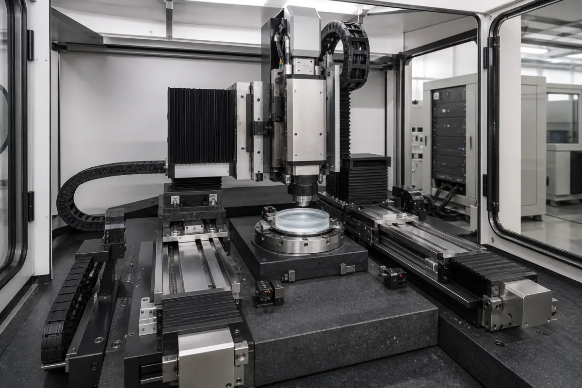
CNC motion system of an optics polishing machine: linear axes on ballscrews or linear motors, the B and C rotary axes, travel, accuracy and straightness
The linear and rotary axis stack of CNC optics polishing machines · X, Y, Z on rails with ground ballscrews or linear motors, B swing and C work axes, 3,000 mm/min, <10 µm positioning and <5 µm repeatability, Y travel of 6 mm against 400–700 mm on freeform machines
On a CNC polishing machine for lenses and mirrors, the motion system is the set of slides, drives, encoders and rotary axes that carries the polishing tool across the part and holds it at the right angle to the surface. Three choices define it: which axes the machine has and how far each travels, whether the linear axes are driven by ballscrews or linear motors and read by rotary or linear encoders, and what positioning, repeatability and straightness the builder guarantees.
The axis hardware of CNC polishing machines for optical lenses, aspheres, freeforms and mirrors: linear X, Y and Z slides on profile rails, ballscrew and linear-motor drives, rotary and linear encoders, counterbalancing, B (tool swing) and C (work) rotary axes, travel ranges, velocity and acceleration, positioning accuracy, repeatability, straightness, squareness, and the greasing of screws and guideways. The CNC control unit, its NC kernel, look-ahead and operator panel are covered on the CNC controller page, simultaneous five-axis control with RTCP on the 5-axis CNC controller page, encoder interface modules on the Feedback interface for CNC axes page and machine-side PLC I/O on the CNC input/output module page; press brake controls and trunnion-table machining centres have their own pages. Rail-and-screw components sold as parts are covered on the Linear motion system and Linear guideways and ball screws installed together on a CNC machine axis pages, and the linear-motor gantry of pick-and-place machines on the XY motion system of an SMT placement machine page. The polishing spindles themselves are covered on the Polishing spindle assembly page, the complete polishers on the Precision optical lens polishing machine page and tool loading on the Polishing-pressure control mechanism page.
CNFX editorial research · Sources checked October 13, 2026 · 5 sources
Five axes on an UltraForm polisher, seven on a precessed-bonnet machine, and how far each one travels
OptiPro's UltraForm Finishing machines move a belt-wrapped polishing wheel in five axes: X, Y and Z slides, a B axis that swings the tool from −60° to 60° or −90° to 90°, and a C work axis with full 360° position and hold. [5] Zeeko's IRP machines carry the tool spindle on two geared rotary axes, A and B, that swing it about a virtual pivot, with the work spindle on the X, Y and Z slides; on the IRP200 the A axis covers −55° to +110° and the B axis ±180°, both at up to 25 rpm. [3]
The Y travel in OptiPro's table tracks what the machine is offered for: the two PRO UFF models with 6 mm of Y list freeform fabrication as not available, while the UFF 300 and UFF 500, with 400 and 700 mm, list it as an option; asphere fabrication is standard on all four. [5] Zeeko gives the IRP100's X axis an asymmetric range so the operator can load and unload the part, and warns that Y travel may be limited at the ends of X travel. [1]
Ask for the travel of every axis at the extremes of the others, the B-axis range needed to reach the edge of your steepest asphere, and whether freeform work needs the long-Y version.
02
Ground ballscrew with a motor encoder or linear motor with a linear scale: same IRP100 accuracy figures
Zeeko sells the IRP100 in two drive versions and publishes the same axis figures for both. In the ballscrew version each axis runs on a pair of THK profile rails driven by a servo motor through a Ø16-5 precision ground ballscrew, with position read from the motor's absolute rotary encoder. [1] In the linear-motor version X and Z are driven directly by linear motors with absolute linear encoders, and the vertical Y axis adds a servo-driven ballscrew and spring as a counterbalance. [2]
With identical published accuracy, what separates the two IRP100 versions on paper is the drive and where position is read: at the motor, through the screw, in one case, and at the slide in the other. [1][2] Editorial calculation: 3,000 mm/min is 50 mm/s, which an axis reaches in 0.2 s at 250 mm/s², covering 5 mm; with 5 mm to accelerate and 5 mm to stop, about 150 mm of the IRP100's 160 mm X stroke can run at full speed.
Zeeko's maintenance manual for the ballscrew IRP100 recommends re-greasing the ballscrews and linear guideways every 6–12 months depending on usage, and in a note on the same page recommends greasing the screws and oiling the guideways every 3 years; the two intervals should be confirmed with the builder. [4]
Ask for positioning accuracy and repeatability with the measuring method (laser interferometer, ISO 230-2 or the builder's own), where the encoder reads (motor or slide), how the vertical axis is counterbalanced, and the greasing interval for screws and guides.
03
Data for an optics polishing machine motion system
Paste it into your enquiry below or into an email to a maker, then replace every bracket.
Parts: [diameter; sag; asphere or freeform; mass]
Axes: [X, Y, Z travel; B and C ranges; extra rotary axes]
Drives: [ballscrew size and grade or linear motor; counterbalance]
Feedback: [rotary or linear encoder; resolution]
Accuracy: [positioning; repeatability; straightness; squareness; test method]
Dynamics: [max velocity; acceleration]
Environment: [slurry protection of rails and screws; greasing interval]
Explore company information and manufacturing capabilities, then discuss the scope of your project with a relevant supplier.
Share this page
Compiled and source-reviewed by the CNFX editorial team.
Each manufacturer above links to the page on that company's own website where the product is listed, with the date we checked it. How we source and review
· Page last updated 13 October 2026
Buyer questions
Do linear motors make an optics polisher more accurate than ballscrews?
Not on Zeeko's published figures: the IRP100 lists <10 µm positioning accuracy and <5 µm repeatability for both its ballscrew and linear-motor versions; the linear-motor version reads position with absolute linear encoders. [1][2]
How many axes does a CNC aspheric polisher have?
OptiPro's UltraForm machines have five: X, Y, Z, a B swing axis and a C work axis. Zeeko's IRP machines add A and B axes that swing the tool spindle about a virtual pivot. [5][3]
Why does Y travel matter on a polishing machine?
In OptiPro's range, models with 6 mm of Y travel do not offer freeform fabrication; the UFF 300 and UFF 500, with 400 and 700 mm, offer it as an option. [5]
How often are the ballscrews and guides greased?
Zeeko's IRP100 manual recommends every 6–12 months depending on usage, and a note on the same page gives 3 years; confirm with the builder. [4]
Sources and what still needs a direct check
Sources checked 2026-10-13. Specification manuals from Zeeko (UK) for the IRP100 in ballscrew and linear-motor versions and for the IRP200, Zeeko's IRP100 maintenance manual, and OptiPro Systems' (USA) UltraForm Finishing specification table.