Editorial Technical Reference

High-Frequency Ceramic Capacitor

This page explains how High-Frequency Ceramic Capacitor is classified within Electronic Component Manufacturing. Technical values and manufacturer relationships are research references; confirm the current specification and supplier evidence for each order.

Technical Definition & Core Assembly

Miniaturized capacitor using ceramic dielectric for high-frequency electronic circuits

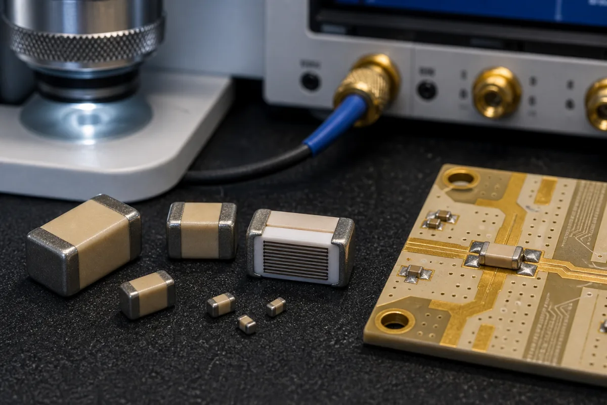
High-Frequency Ceramic Capacitor in a manufacturing environment
Representative product image. Confirm appearance and specifications with the manufacturer.

Product Specifications

Technical details and manufacturing context for High-Frequency Ceramic Capacitor

Definition
A high-frequency ceramic capacitor is a ceramic-dielectric capacitor selected for controlled impedance, loss and resonance in an RF, microwave or other fast-signal circuit. The category can include surface-mount multilayer, single-layer or other series-specific constructions; it does not identify one dielectric formulation, electrode system or termination. Class 1 temperature-compensating MLCCs such as C0G are common, but “high frequency” alone does not prove C0G, barium titanate, nickel electrodes, AgPd terminations, RoHS status or a fixed performance range. For a surface-mount Class 1 multilayer ceramic capacitor, IEC 60384-21 is the relevant sectional specification; IEC 60384-8 explicitly excludes that construction. Capacitance, tolerance, rated voltage, temperature characteristic, dissipation factor/Q, insulation resistance, proof voltage, operating temperature, aging, self-resonance, ESR, current capability, case code, termination and mass are part-number and test-condition specific. The listed values are unverified comparison prompts, not one data sheet. RF selection must use the exact manufacturer impedance/S-parameter model, mounting geometry, DC/AC bias, temperature, power and reliability evidence.
Working Principle
Electric field energy is stored between electrodes separated by the ceramic dielectric. At frequency, the mounted part behaves as a network of capacitance, dielectric/electrode loss and parasitic inductance/resistance rather than an ideal capacitor. Its impedance falls, reaches self-resonance, then becomes inductive; additional resonances can follow. The useful range depends on capacitance and tolerance, dielectric, case and electrode geometry, termination, PCB land/via layout, fixture/de-embedding, bias, signal level, temperature and aging. A generic multilayer description does not establish high-Q or microwave performance.
Common Materials
Ceramic dielectric (series-specific formulation), Internal electrode system (series-specific), Termination and barrier/plating system (series-specific)
Technical Parameters
ParameterTypical rangeNotes & selection driver
CapacitanceRequired0.5–10000 pFNominal capacitance at specified frequency
Voltage RatingRequired16–100 VMaximum DC working voltage
Temperature CoefficientRequired0±30 ppm/°CCapacitance change with temperature
Dissipation FactorRequired≤0.001 %Loss tangent at 1MHz
Self-Resonant Frequency0.5–10 GHzFrequency where capacitor becomes inductive
Case Size CodeRequired0402–1210Case-size code; confirm inch/metric convention, body dimensions and PCB land pattern in the selected manufacturer drawing
Insulation Resistance≥10 At 25°C, rated voltage
Dielectric Withstanding Voltage2.5× rated V DC1–5 s, 50 mA max
Operating Temperature Range-55–125 °CClass 1 dielectric
Capacitance Tolerance±5, ±10 %Tighter on request
Aging Rate≤0.1 % per decade hourLogarithmic time aging; confirm dielectric, reference time, preconditioning and model data
Termination FinishAgPd or Ni/SnFinish option; material stack and regulatory compliance require an exact-part declaration
Weight0.5–50 mgPer piece, package dependent

Ranges are indicative industry figures for RFQ preparation, not a supplier commitment. Confirm every value and standard with the legal manufacturer before ordering.

Components / BOM
  • Ceramic Dielectric Part
    Insulating material that determines capacitance and frequency characteristics
    Material: Barium Titanate or Titanate-based ceramic
  • Internal Electrode Part
    Conductive layers that form capacitor plates
    Material: Nickel or Copper
  • Termination Part
    External connection points for circuit mounting
    Material: Silver Palladium alloy
  • Protective Coating Optional Part
    Surface protection against environmental factors
    Material: Epoxy resin

Industry Taxonomies & Aliases

Commonly used trade names and technical identifiers for High-Frequency Ceramic Capacitor.

Industrial Ecosystem & Supply Chain Structure

Complementary Systems
Downstream Applications
Specialized Tooling

Application Fit & Sizing Matrix

Operational Limits
model: Use part-number impedance/S-parameter data with fixture/de-embedding, PCB geometry, bias, temperature and signal level.
circuit: Define matching, filtering, coupling, timing or decoupling function and the required impedance over frequency.
electrical: Set capacitance/tolerance, DC/AC voltage and current, Q/ESR, SRF, insulation and temperature behaviour at stated conditions.
mechanical: Choose case code/convention, thickness, termination, land pattern, flex robustness and assembly process from one drawing.
reliability: Define humidity, thermal cycling, vibration/flex, surge/pulse and application qualification evidence.
Sizing Data Required
  • Select dielectric/temperature characteristic before comparing nominal capacitance
  • Keep operating voltage and proof-voltage test conditions separate
  • Verify Q/ESR/SRF at the intended frequency and mounting
  • Check RF current/power heating and DC-bias dependence where applicable
  • Confirm case-code convention, land pattern, reflow and compliance declaration

Reliability & Engineering Risk Analysis

Failure Mode & Root Cause
RF response misses the design target
Cause: Nominal capacitance was selected without part-specific impedance, ESR/Q, SRF, tolerance, layout and bias/temperature data.
Crack, short or open circuit develops
Cause: PCB flex, depaneling, placement, soldering thermal/mechanical stress or electrical overstress exceeds the exact construction capability.
Capacitance/loss drifts outside budget
Cause: Dielectric characteristic, aging reference, DC/AC bias, temperature, humidity or preconditioning was omitted.
Maintenance Indicators
  • Measured impedance/resonance/Q differs from the qualified build
  • Leakage/insulation resistance changes or intermittent/open/short behaviour appears
  • Visible termination/body damage, abnormal heating or circuit detuning
Engineering Tips
  • Simulate and measure the exact part in the intended PCB fixture and operating conditions.
  • Follow manufacturer land, placement, reflow, flex and handling guidance.
  • Qualify electrical and environmental margins using the exact series/detail specification.

Indicative industry ranges for design and RFQ preparation. Confirm the exact figures and applicable standard with the manufacturer before specifying.

Compliance & Manufacturing Standards

Applicable Standards
IEC 60384-1:2021 is the generic fixed-capacitor specification for terms, inspection and test methods used with sectional/detail specifications. IEC 60384-21:2024 applies to fixed unencapsulated surface-mount multilayer ceramic capacitors with defined temperature coefficient, dielectric Class 1. It supplies preferred characteristics, assessment procedures and general requirements, not evidence that every page value belongs to one part. IEC 60384-8:2024 applies to Class 1 ceramic capacitors but explicitly excludes fixed surface-mount multilayer ceramic capacitors; it must not be used for this page’s SMD MLCC values. EIA-198 concerns ceramic dielectric capacitor classes, characteristics and requirements, not a universal 0402–1210 millimetre dimension. MIL-PRF-55681 and AEC-Q200 apply only with exact qualified product/family evidence; AEC-Q200 is qualification, not an automatic certification label.

Quoted from the published standard.

Manufacturing Precision
  • No universal ≤0.001% loss, ≥10 GΩ, 2.5× proof voltage, ≤0.1% aging, 10–30 kV/mm breakdown, 0.1% strain, 100 °C/min shock, 0.5 Vrms resonance or <10 mΩ ESR limit is asserted. Use exact detail specification and model data.
Quality Inspection
  • Confirm part number, dielectric/temperature code, case convention, dimensions, termination and compliance declaration.
  • Measure capacitance, loss/Q, impedance/SRF or S-parameters using stated fixture, frequency, level, bias and temperature.
  • Verify proof, insulation, soldering/flex and environmental qualification to the applicable exact specification and application.

Manufacturers of High-Frequency Ceramic Capacitor

3 companies list this product among what they make. Company figures are quoted from each company's own website; every card states where the relationship came from.

Cixi AnXon Electronic Co., Ltd
Cixi, Zhejiang, CN
Listed on the company's own website · profile compiled by CNFX from public sources
Listed there as: “HV Multilayer Ceramic capacitor MLCC”
View source page ↗ anxoncap.com · checked 2026-09-04
Fujian Torch Electron Technology Co.,Ltd
Quanzhou, Fujian, CN
Listed on the company's own website · profile compiled by CNFX from public sources
Listed there as: “Three Terminal Chip Multilayer Ceramic Capacitor”
View source page ↗ torchcapacitor.com · checked 2026-09-04
UF Capacitors Factory Co., LTD
Dongguan, Guangdong, CN
Listed on the company's own website · profile compiled by CNFX from public sources
Listed there as: “CT4 Radial Multilayer Ceramic Capacitor”
View source page ↗ ufcapacitors.com · checked 2026-09-04

Manufacturer listings support early research and capability understanding. They are not certification, ranking, or transaction guarantees.

Share this page
Technical documentation
Request current drawings, revision history, and a signed specification sheet.
Manufacturing capability
Verify equipment lists, process limits, capacity, and representative production evidence.
Inspection readiness
Confirm test methods, calibrated equipment, sampling plans, and traceable reports.
Supplier transparency
Check the legal entity, factory address, ownership, certifications, and direct contacts.

CNFX does not score or rank suppliers. Buyers must verify all claims and documents with the legal manufacturer before ordering.

Frequently Asked Questions

Does this category guarantee 0.5–10000 pF, 16–100 V and 0±30 ppm/°C in one series?

No. These values span possible products and may not coexist. Select one part number and verify capacitance, voltage, temperature code, tolerance, loss/Q and all measurement conditions.

Does IEC 60384-8 apply to 0402–1210 surface-mount multilayer capacitors?

No. IEC 60384-8:2024 explicitly excludes fixed surface-mount multilayer ceramic capacitors. Class 1 SMD MLCCs are covered by IEC 60384-21; the exact detail specification and part evidence still determine values.

Are 0402 and 1210 millimetre dimensions defined by EIA-198?

No. They are case-size codes whose inch/metric convention must be stated and converted using the selected manufacturer drawing. EIA-198 concerns ceramic dielectric capacitor characteristics and requirements, not a body-dimension guarantee for this row.

Does AgPd or Ni/Sn termination prove RoHS or RF suitability?

No. Obtain the exact construction/material declaration and regulatory statement. RF suitability additionally requires impedance, ESR/Q, self-resonance or S-parameter data in the intended mounting and bias conditions.

Data Basis

Editorial classification, named public sources where available, and source-reviewed manufacturer records.

Preliminary Technical Classification
This page supports structured research, RFQ preparation, and supplier evaluation. It does not replace buyer-led supplier qualification, standards review, or technical approval.
Buyer enquiry

Request manufacturing insight for High-Frequency Ceramic Capacitor

Ask for use case, specification boundaries, supplier type, and RFQ preparation information for this product.

Where it goes
Straight to the CNFX editorial desk, and to the manufacturer if this product is linked to a claimed profile. Nothing is broadcast to a supplier list.
Your details stay here
We do not sell or rent enquiry data, and we do not add you to a mailing list. Used only to answer this request.
No commission, no middleman
CNFX is a directory. We take no cut of any order and never negotiate on a supplier's behalf.
What we don't claim
A listing is not an endorsement. Qualify every supplier and verify every figure yourself before ordering.

Your business information is used only to process this request.

Thank you! Your message has been sent. We'll respond within 1–3 business days.
Sorry, we couldn't send your message. Please try again, or email us at [email protected].

Need to Manufacture High-Frequency Ceramic Capacitor?

Compare manufacturer profiles with relevant product and process capability.

Previous Product
High-Density Interconnect (HDI) PCB Substrate
Next Product
Surface Mount Capacitor
Get QuotesChat