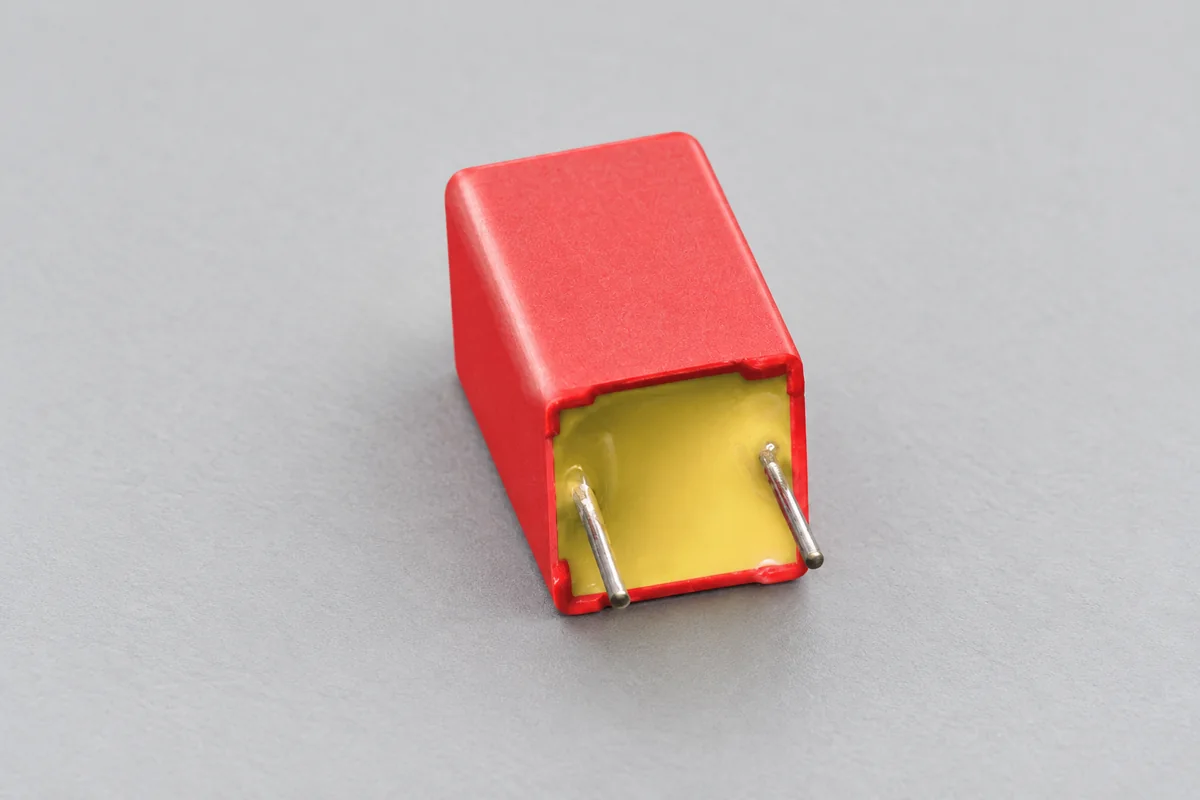
Plastic film capacitors for power, pulse and signal circuits · PET vs PP vs PPS dielectric, film/foil vs metallised, self-healing, dissipation factor and insulation resistance, rated voltage and temperature, du/dt pulse rating, AC and mains use
A film capacitor uses a thin plastic film — polyester, polypropylene or PPS — as its dielectric, wound with metal foil or metallised layers, to give stable, low-loss, self-healing capacitors for power electronics, snubbers, filters and signal circuits. Ask three things first: which dielectric suits the frequency, losses and temperature; whether film/foil or metallised construction suits the current and pulse stress; and what voltage, du/dt and mains-safety ratings apply.
Plastic film capacitors — PET, PP and PPS, film/foil and metallised — for DC-link, snubber, pulse, AC, interference-suppression and signal circuits, through-hole and SMD. Ceramic, tantalum and aluminium electrolytic capacitors, power factor correction capacitor banks and supercapacitors are outside this page except where compared.
CNFX editorial research · Sources checked October 11, 2026 · 4 sources
Choose the dielectric for losses, stability and temperature
WIMA's dielectric comparison gives polyester (PET) a dielectric constant of 3.3, operation from −55 to +105 °C (+125 °C), dissipation factor of 0.8%, 1.5% and 3.0% at 1, 10 and 100 kHz, insulation resistance of 10,000 MΩ·µF at 25 °C and 1,000 at 85 °C, and capacitance change of ±5% over temperature. Polypropylene (PP) has a dielectric constant of 2.2, −55 to +105 °C, dissipation factor of 0.05%, 0.08% and 0.25%, insulation resistance of 100,000 and 10,000 MΩ·µF, and ±2.5% change; PPS has 3.0, −55 to +140 °C, 0.2–0.5% and ±1.5%. All three self-heal, and WIMA's table gives their typical end-of-life failure mode as open, against short for ceramic X7R and tantalum. [2]
Vishay describes polyester as the general-purpose film with the best volume efficiency at moderate cost for DC decoupling, blocking, bypassing and noise suppression; polypropylene as having very low dielectric losses, high insulation resistance, low dielectric absorption and very high dielectric strength for high-frequency, high-voltage, AC, pulse and interference-suppression use; and PPS for higher temperatures with low dissipation factor. [1] WIMA lists PET for decoupling, coupling and blocking and PP for sample-and-hold, resonant circuits, power supplies, converters, lighting and audio. [2]
Editorial calculation: at 1 kHz PET's 0.8% dissipation factor is 16 times PP's 0.05%; PP's 100,000 MΩ·µF means a 1 µF capacitor has about 100 GΩ insulation resistance (a 100,000 s time constant) at 25 °C, falling tenfold at 85 °C. [2]
Give the supplier the capacitance and tolerance, dielectric (PET, PP, PPS), rated DC and AC voltage, application (DC-link, snubber, resonant, filter, mains X/Y), ripple current and frequency, du/dt or pulse current, operating temperature and lifetime, humidity class, mounting (THT pitch or SMD), case and lead style, approvals (for example X/Y safety certification), and quantity.
02
Choose construction and rate for voltage, pulses and AC
Vishay divides film capacitors into film/foil types — two metal foils separated by film, with high insulation resistance, excellent current and pulse handling and good capacitance stability — and metallised types, whose electrodes are vacuum-deposited layers of 0.02–0.1 µm, giving high volume efficiency and self-healing: an arc at a flaw evaporates the thin metallisation around it and isolates the fault. Special designs include heavy-edge or double-sided metallisation, mixed film/foil and metallised construction, and internal series connection for high voltage. [1]
Rated voltage is the maximum DC, AC or pulse voltage applied continuously up to +85 °C and must be derated above that. The pulse rise time du/dt, in V/µs, expresses the steepest permitted voltage gradient, depends on dielectric, film thickness and construction, is tested at 5 to 10 times the datasheet value, and can be higher when pulse voltage is below rated voltage. AC ratings assume clean sine waves without transients, so standard types must not be used across the mains — capacitors designed for mains operation are the X and Y (RFI) types — and AC voltage must be derated with frequency to keep surface temperature rise within 10 °C. Capacitance is measured at 1 kHz, insulation resistance after one minute at 20 °C and 50% RH, and high humidity can lower insulation resistance and raise capacitance. [1]
Editorial note: for DC-link or snubber use, ask for ripple current versus frequency, ESR and du/dt on the exact part, since these come from the construction rather than the dielectric alone.
03
Compare what suppliers offer
Suppliers linked to this page list film capacitors; each card links to the page reviewed.
Listings include metallised film capacitors, DC-link and high-voltage film capacitors for new-energy and power electronics, plastic film capacitors for consumer electronics, and film capacitors for pumps and motors; ask each for dielectric, construction, du/dt, ripple current, lifetime test data and safety approvals.
04
Check a DC-link capacitor's ripple current, ESR and core temperature
Cornell Dubilier's Type 947D data sheet for polypropylene DC-link capacitors covers 130 to 1500 µF at ±10%, 900 to 1300 Vdc, −45 °C to 85 °C ambient, to IEC 61071. Test voltages are 150% of rated DC for 10 s between terminals and 4 kVac for 10 s to case; the life test is 7000 h at 85 °C and rated voltage, and life expectancy is 350,000 h at a 60 °C core and rated voltage. [4]
Its table lists the 947D311K901ACGSN at 310 µF, 900 Vdc, 85 × 75 mm, with Irms of 67 A at 55 °C ambient, ESR of 1.4 mΩ (the 10 kHz value), thermal resistance of 1.4 °C/W core-to-case and 3.8 °C/W case-to-ambient in still air. Core temperature is TC = TA + I²(ESR/1000)Θ, with Θ the sum of the two resistances; the rise may not exceed 40 °C nor the core 95 °C. [4]
Editorial calculation: at 67 A, 67² × 1.4/1000 ≈ 6.3 W, and 6.3 W × 5.2 °C/W ≈ 32.7 °C rise, so the core reaches about 87.7 °C at 55 °C ambient, inside both limits. Ask each supplier for ESR at a stated frequency and both thermal resistances. [4]
05
Check the climatic category, humidity test and storage limits
TDK's general technical information for film capacitors (October 2025) explains the climatic category printed on datasheets, for example 55/100/56, as specified in IEC 60068-1. The first figure is the lower category temperature (−55 °C), the second the upper category temperature (+100 °C), and the third the duration in days of damp heat test Cab, run at (93 ±3)% relative humidity and 40 ±2 °C; limit values after that test are given in each datasheet. TDK warns that AC self-heating raises the surface temperature above ambient, so the upper category temperature must not be exceeded, and that long contact with humidity, liquid water or dew will remove the film metallisation and destroy the capacitor. [3]
TDK uses this severity table to compare accelerated humidity tests with the 40 °C/93% reference, so an 85 °C/85% RH result is not equivalent to the damp heat days in the climatic category; ask which test, duration and post-test limits a supplier's humidity claim rests on. [3]
TDK states its capacitors can be used down to 40 kPa without voltage derating, corresponding to an altitude of 7000 m (approx. 23000 ft), with higher-altitude use on special request. For long storage it gives −40 to +40 °C, a maximum of 80% relative humidity with no dew on the capacitor, and a maximum of 5 years unless the datasheet says otherwise. [3]
Fill the specification fields with values for your circuit
A film capacitor quotation needs values for your circuit. The table explains each field, gives published values where a reviewed source states them, and says what to obtain from the supplier.
Explore company information and manufacturing capabilities, then discuss the scope of your project with a relevant supplier.
Compiled and source-reviewed by the CNFX editorial team.
Published product pages show what a company offers, not tested performance. Confirm the legal seller, factory and scope for your order. How we source and review
· Page last updated 11 October 2026
Is polypropylene or polyester better for a film capacitor?
Polypropylene has far lower losses (0.05% vs 0.8% DF at 1 kHz in WIMA's table) for AC, pulse and high-frequency use; polyester gives smaller, cheaper capacitors for DC decoupling and blocking. [2][1]
What does self-healing mean in a film capacitor?
Vishay explains that an arc at a film flaw evaporates the thin metallisation around it, isolating the fault. [1]
Can any film capacitor be connected across the mains?
No: Vishay says standard types must not be used across the line; X and Y RFI capacitors are designed for mains operation. [1]
What does a climatic category such as 55/100/56 mean on a film capacitor?
TDK explains it as a −55 °C lower and +100 °C upper category temperature plus 56 days of damp heat testing at (93 ±3)% relative humidity and 40 ±2 °C. [3]
How can I check that a DC-link film capacitor will not overheat?
Cornell Dubilier's 947D data sheet computes core temperature as ambient plus I² × ESR × total thermal resistance, and limits the rise to 40 °C and the core to 95 °C. [4]
Sources and what still needs a direct check
Sources checked 2026-10-11. Vishay and WIMA make film capacitors and describe their own technology; WIMA's comparison values are typical. Datasheet values for the exact part govern a design.