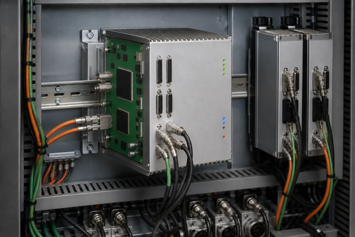
Automation · Axes, pulse or fieldbus output, synchronisation, interpolation and I/O
A motion controller plans moves and commands servo or stepper drives on one or more axes. Ask three things first: how many axes and what kind of coordinated motion, whether the drives take pulse/direction or a fieldbus such as EtherCAT, and what speed, resolution and I/O the machine needs.
Standalone and card-type motion controllers and motion modules for machines, stages and robots, with pulse or fieldbus outputs. Servo drives, motors, PLCs without motion functions and complete CNC systems are outside this page.
CNFX editorial research · Sources checked October 12, 2026 · 4 sources
Beckhoff's EL2521 pulse-train terminal shows what a pulse output involves: one channel with A and B outputs, pulse-direction, frequency modulation and AB encoder simulation modes, a base frequency of 0–500 kHz (50 kHz default), up to 15-bit resolution, 5–24 V DC output and synchronised operation through EtherCAT distributed clocks. [1]
Editorial calculation: in pulse/direction mode, motor speed = pulse frequency ÷ pulses per revolution. At 500 kHz and 10,000 pulses per revolution, that is 50 rev/s or 3,000 rpm; on a 10 mm-lead screw, each pulse moves 10 ÷ 10,000 = 0.001 mm and top speed is 500 mm/s. [1] Raising pulses per revolution improves resolution but lowers top speed for the same pulse frequency.
Fieldbus controllers send setpoints to drives over the network instead of pulses: Fuyu's FMCG6A six-axis controller, for example, supports Modbus, CANopen and EtherCAT alongside pulse outputs. [2] Confirm which protocol and drive profile your servo drives support.
Give the supplier the number and type of axes, drive and motor models, pulse or fieldbus interface, required speed and resolution, coordinated motions (interpolation, gearing, camming), feedback, I/O count, programming language and host system, supply and mounting.
02
Check axes, interpolation, I/O and software
Fuyu's FMCG6A lists six axes, single-axis, linear and circular interpolation, homing, hardware positive and negative limit inputs, differential encoder inputs, eight general I/O channels with expansion, RS232, RS485, CAN, EtherCAT and Ethernet ports, programming from C/C++, C# or Python on Windows or Linux, firmware update from a host computer, 24 V DC supply and 4 W consumption. [2]
Galil's DMC-4000 shows how the servo update period lengthens as axes are added: the controller handles 1 to 8 axes from a 20–80 V DC supply, and its minimum servo update rises from 62 µs for 1–2 axes to 187.5 µs for 7–8 axes. Galil lists independent positioning, jogging, linear and circular (vector) interpolation, electronic gearing and cam, PVT and contour modes, quadrature, BiSS and SSI encoders, and 11 µs command processing. [4]
Editorial calculation: 62 µs corresponds to an update rate of about 16 kHz and 187.5 µs to about 5.3 kHz, and 62 ÷ 187.5 = 0.33, so an eight-axis configuration updates each servo loop at one-third the rate of a two-axis one. [4]
Ask for the servo update cycle, the number of axes that can be interpolated together and any limits on look-ahead or path blending, and check them against the moves your machine makes.
Check fieldbus timing when the controller drives over EtherCAT
The EtherCAT Technology Group's technology overview states that EtherCAT, disclosed in IEC 61158, was developed for short cycle times (100 µs or less), low jitter for accurate synchronisation (1 µs or less) and low hardware cost. Each node reads and inserts its data on the fly as the frame passes, giving an effective data rate above 90% of the 100 Mbit/s link, and up to 65,535 devices can sit in one segment, with up to 100 m of cable between nodes in 100BASE-TX. [3]
The overview explains that velocity is derived from measured position, so position samples must be taken at exactly equal intervals; with distributed clocks the position measurements are triggered by each node's local clock rather than by frame arrival, which lets a software master on standard Ethernet hardware hold accuracy despite a few microseconds of send jitter. Compare this with pulse-train outputs, where timing depends on the pulse frequency the controller can generate. [3][1]
Editorial calculation: at a 100 µs cycle a controller closes 10,000 position updates per second per axis; 1 µs of timing error is 1% of that cycle.
EtherCAT feature (ETG overview)
Value or function
Design cycle time
≤ 100 µs
Synchronisation jitter (distributed clocks)
Significantly below 1 µs; propagation delay measured and compensated per node
Devices per segment
Up to 65,535
Cable between nodes (100BASE-TX)
Up to 100 m
Topologies
Line, tree, star or daisy-chain; hot connect of segments
Drive profiles
CAN application protocol over EtherCAT (CoE); servo drive profile per IEC 61491-7-204 (SoE)
State the drive network (pulse or EtherCAT and its profile), the number of axes and the cycle time you need, and ask for the controller's minimum cycle time, distributed-clock support and drive profile compatibility.
04
Compare what suppliers offer
Suppliers linked to this page list motion controllers for machines, stages and inspection systems. [2]
Fuyu lists multi-axis controller cards for its linear motion systems; JMC lists pulse-type and EtherCAT motion controllers with servo motors; Finger lists motion controllers and open CNC platforms; Hollysys lists MC motion controllers with its PLCs; JWIPC lists motion controllers among industrial PCs; JY Instrument lists servo motion control systems for positioning stages; Pomeas lists motion controllers for vision systems; LaiYin lists CMM motion controllers; Faith lists motion controllers among machinery. [2]
05
Trace the controller components
This is a functional reference built from the sources cited; it is not one maker's parts list.
Fill the specification fields with values for your machine
A motion controller quotation needs values for your axes and drives. The table explains each field, gives published values where a reviewed source states them, and says what to obtain from the supplier.
Field
What it means and published values
Ask the supplier for
Number of axes
E.g. 6 axes [2]; 1–8 axes on one controller family. [4]
Axes and interpolated axes.
Control cycle time (ms)
Servo or interpolation update; e.g. 0.062 ms (1–2 axes) to 0.1875 ms (7–8 axes) on one controller. [4]
EtherCAT designed for ≤100 µs cycles and <1 µs jitter with distributed clocks. [3]
Minimum cycle time; DC support; profiles.
07
Send the axes, drives and motion data together
Paste it into your enquiry below or into an email to a maker, then replace every bracket.
Axes: [number; linear or rotary; interpolated groups]
Drives: [models; pulse/direction or fieldbus; drive profile]
Motion: [speeds; resolution; interpolation; gearing or camming]
Feedback: [encoder type and resolution]
I/O: [limits; home; general inputs and outputs]
Software: [language; host OS; PLC or PC integration]
Hardware: [supply; mounting; temperature]
Explore company information and manufacturing capabilities, then discuss the scope of your project with a relevant supplier.
Share this page
Compiled and source-reviewed by the CNFX editorial team.
Published product pages show what a company offers, not tested performance. Confirm the legal seller, factory and scope for your order. How we source and review
· Page last updated 13 October 2026
Buyer questions
Pulse/direction or EtherCAT motion control?
Pulse outputs are limited by pulse frequency, which caps speed for a given resolution; fieldbus controllers send setpoints over the network and can synchronise axes with distributed clocks. [1][2]
How fast can a pulse-controlled axis run?
Speed equals pulse frequency divided by pulses per revolution; 500 kHz at 10,000 pulses per revolution gives 3,000 rpm. [1]
What functions should a multi-axis controller have?
One six-axis controller lists linear and circular interpolation, homing, limit inputs, encoder feedback and expandable I/O; check which of these your machine needs. [2]
How fast can an EtherCAT motion network cycle?
The EtherCAT Technology Group states the design targets cycle times of 100 µs or less with synchronisation jitter of 1 µs or less, using distributed clocks. [3]
Does the servo update rate change with the number of axes?
On Galil's DMC-4000 it does: the minimum servo update is 62 µs for 1–2 axes, 125 µs for 3–4, 156.25 µs for 5–6 and 187.5 µs for 7–8 axes. [4]
Sources and what still needs a direct check
Sources checked 2026-10-12. Beckhoff is an automation maker; its terminal data sheet shows pulse-output limits. Galil Motion Control publishes servo-update and I/O figures for a 1–8-axis controller. The EtherCAT Technology Group describes fieldbus timing. Fuyu is a supplier listed on this page; its values are catalogue figures.