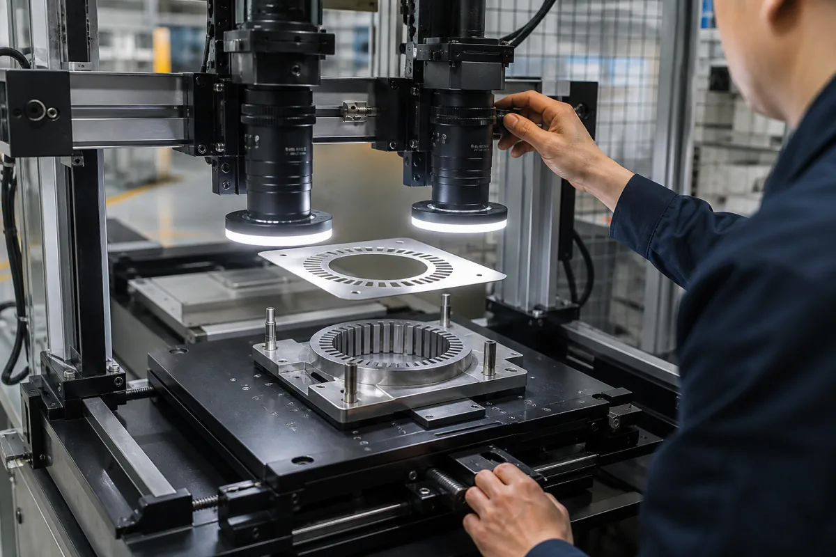
Alignment vision system for stacking core laminations: a wide-field camera that finds the top sheet and two fine cameras that locate its holes before the gripper picks it
Camera guidance for core lamination stackers · a wide-field camera for the sheet pile, two fine cameras on the sheet's holes, nine-point calibration, ±2.5 mm and ±0.1 mm targets, and gripper cameras against centring tables
A stacker gripper can only put a lamination where the core design wants it if it knows where that lamination is before it picks it up. In the truss stacker described below, one camera finds the pile and its angle, two more look closely at the two locating holes of the top sheet, and the controller turns the two hole centres into a pick position and rotation for that sheet.
Vision subsystems that locate electrical-steel laminations for automatic transformer and reactor core stacking: coarse pile-finding cameras, fine cameras on locating holes or edges, camera calibration to machine coordinates, the hand-off to the PLC, and how their accuracy is tested. Camera-based inspection, measurement and guidance systems are covered on the Machine vision system for inspection page. The stacking machines themselves are covered on the Transformer core lamination stacking machine page, pick-and-place heads that place stator sheets over guide rods on the Precision stacking head for stator laminations page, and the robot that clamps and carries a finished core on the Transformer core clamping and handling robot page. Cameras that position optical lenses for loading are a different product on the Vision/sensor system for lens loading page.
CNFX editorial research · Sources checked October 13, 2026 · 3 sources
One camera for the pile, two for the holes: ±2.5 mm over a 1 m × 0.8 m field and ±0.1 mm in two 100 mm fields
Liu Jing and Zhang Jingxiao of CECEP Xi'an Qiyuan Mechanical and Electrical Equipment describe, in Electrical Engineering (电气技术) 26(1), 2025, the vision system of a three-axis truss stacker built for offline stacking of large transformer cores. It splits the job between two vision stages, each with its own accuracy target and field. [1]
The PLC combines the two hole positions with preset reference positions to calculate where the gripper should pick, and the vision system exchanges trigger commands and fitted geometry with the PLC over socket communication. The sheet centre is taken as the midpoint of the two hole centres; the vertical axis is left out of the vision error because the servo axis holds it. [1]
Editorial calculation on the two-hole layout: with the holes about 500 mm apart, as in the authors' test sheets, a 0.1 mm error in the cross position of one hole turns the calculated sheet angle by about 0.011°. [1]
Editorial calculation on the fine camera: a 100 mm field at the paper's calibrated 0.025 mm per pixel needs about 4,000 pixels across. Basler's acA4024-29um, for example, has a 4024 × 3036 pixel, 12.2 MP sensor with 1.85 µm pixels, which would give about 0.0249 mm per pixel over 100 mm. [1][3]
The two round holes of the top sheet by circle finding and BLOB analysis [1]
State the sheet sizes and hole positions, the pile area the coarse camera must cover, and the pick accuracy required at the holes; the fine camera's field and pixel count follow from those.
02
Nine-point calibration at 0.025 mm per pixel, then hole-spacing tests: within 0.1 mm static and 0.3 mm with the sheet moved
Before the cameras can guide the truss, each is calibrated by imaging nine points of known coordinates, which gives its intrinsic and extrinsic parameters and the conversion from pixels to millimetres. The authors' calibration table gives about 0.0248 mm per pixel for fine camera 1 and 0.0251 mm per pixel for fine camera 2. [1]
Because the error of the sheet centre is hard to observe directly, the authors measure the distance between the two hole centres: the truss captures the left hole, moves 500 mm in X, captures the right hole, and both centres are fitted into truss coordinates. With the sheet held still and only the camera repositioned, a sheet with 499.75 mm hole spacing measured within 0.1 mm over repeated runs. With the sheet moved at random within the field of view, a sheet with 499.7 mm spacing measured within 0.3 mm. [1]
The authors read the 0.3 mm result as a length accuracy of ±0.15 mm, take the length error as twice the hole positioning error, and conclude that pick positioning is about ±0.075 mm, inside the ±0.1 mm design requirement under ideal test conditions. [1] The result is conditional on that reasoning and on laboratory conditions; ask any supplier for the same kind of test on your sheets and pile.
Ask for the calibration method and the mm-per-pixel figure of each fine camera, and for a repeat test on a sheet of known hole spacing, both static and with the sheet moved across the field.
03
Sheets with locating holes and sheets without: a camera on the gripper for hole recognition, or a centring table first
Güdel, which builds robot and gantry core stacking systems for distribution and power transformer cores with side lengths from 0.5 m to more than 10 m, separates the two cases. For sheets with holes, it names the pin on the gripper and a camera on the gripper for hole recognition as crucial for precise stacking; sheets without holes are pre-centred on a centring table and then placed on the stack. [2]
Güdel's stacker software also measures and records the thickness of each sheet as it is picked up, and measures the height of the core in a freely programmable sequence. [2] Where the CECEP system mounts its fine cameras on the truss and moves the truss between holes, Güdel's description puts the camera on the gripper itself. [1][2]
Say whether your laminations carry locating holes; without them, ask whether the stacker uses an edge-finding camera or a mechanical centring table.
04
Data for a lamination stacking vision system
Paste it into your enquiry below or into an email to a maker, then replace every bracket.
Sheets: [grade; thickness; largest and smallest sheet; hole diameter and positions]
Pile: [area to cover; how the pile is presented]
Accuracy: [coarse target; pick target at the holes]
Cameras: [number; mounting on truss, gantry or gripper; field; pixel count]
Calibration: [method; mm per pixel; recalibration interval]
Interface: [PLC or robot controller; protocol]
Explore company information and manufacturing capabilities, then discuss the scope of your project with a relevant supplier.
Share this page
Compiled and source-reviewed by the CNFX editorial team.
Each manufacturer above links to the page on that company's own website where the product is listed, with the date we checked it. How we source and review
· Page last updated 13 October 2026
Buyer questions
How accurate does lamination stacking vision need to be?
In the CECEP truss stacker study, the coarse camera had to locate the pile to ±2.5 mm and the two fine cameras the sheet holes to ±0.1 mm. [1]
Why use two cameras on two holes?
The two hole centres give the sheet's centre as their midpoint and, with them about 500 mm apart in the CECEP tests, its angle as well. [1]
What accuracy was measured in practice?
Hole spacing measured within 0.1 mm with the sheet held still and within 0.3 mm with the sheet moved within the field; the authors derive a pick accuracy of about ±0.075 mm. [1]
What if the laminations have no holes?
Güdel pre-centres sheets without holes on a centring table; for sheets with holes it uses a pin and a camera on the gripper. [2]
Sources and what still needs a direct check
Sources checked 2026-10-13. A 2025 paper by Liu Jing and Zhang Jingxiao (CECEP Xi'an Qiyuan) on a two-hole positioning system for a truss transformer core stacker, Güdel's 2016 article on its core stacking systems, and Basler's acA4024-29um camera documentation.